Rockwell Automation 23P PowerFlex Digital DC Drive User Manual
Page 138
138
Rockwell Automation Publication 20P-UM001K-EN-P - July 2014
Chapter 3
Programming and Parameters
MO
TO
R C
O
NT
ROL
Speed F
ee
dback
426
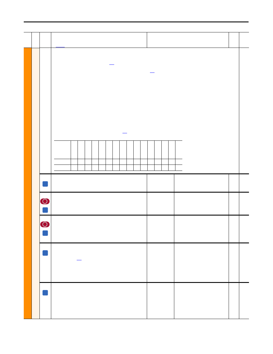
[Resolver Status]
Indicates the status of the resolver module.
• Bit 0 “CableBalSts” - Cable balance tuning process status. 0 = cable balanced (tuned), 1 = cable not balanced or the test is currently active. See
Resolver Cable Balance Tuning Test on page
for details.
• Bit 1 “CableBalTest” - Cable balance tuning test results. 0 = cable balance (tuning) test completed, 1 = cable can't be balanced or the motor was not at
minimum speed during test. See Resolver Cable Balance Tuning Test on page
for details.
• Bit 2 “ReslvrMinSpd” - Module has detected motion greater than the minimum speed. Also permits cable balance tuning test. 0 = motor turning, 1 =
motor not turning.
• Bit 3 “CableCompSts” - Cable length compensation status. 0 = cable length compensation is OK, 1 = cable length compensation failed.
• Bit 4 “Energized” - Indicates the value written to Par 425 [Resolver Config], bit 4 “Energize”. 0 = resolver is not energized, 1 = resolver is energized.
• Bit 8 “Open Wire” - Indicates if a problem with cable wiring or resolver configuration was detected. This bit is also is set if the maximum tracking speed
of the resolver is exceeded (see Table 425A in Par 425 [Resolver Config]). 0 = resolver feedback signals are OK, 1 = resolver has an open wire.
• Bit 9 “PwrSupplySts” - Indicates the resolver module power supply status. 0 = power supply is OK, 1 = power supply has an error.
• Bit 10 “HardwareSts” - Power-up hardware diagnostics status. 0 = diagnostics passed, 1 = diagnostics failed.
• Bit 11 “ParametersOK” - Indicates the resolver configuration parameters status. 0 = a parameter configuration error exists, 1 = parameter
configuration is OK.
• Bit 12 “SSI Comm OK” - Resolver module communication status as determined by the drive. 0 = a communication error exists, 1 = communication is
OK.
• Bit 13 “SSI Comm Err” - Latched indication of three consecutive SSI communication errors (bit 12 = 1) as determined by the drive. 0 = no error. 1 =
three consecutive SSI communication errors have occurred. In this case a “Resolver Error” fault (F93) is displayed and the must be cleared using the
“Clear Faults” function. See Fault Descriptions on page
for more information.
Note: This parameter was added for firmware version 5.002.
431
427
[Reslvr Position]
32-bit indication of resolver position. 16-bit revolution count (upper word) +
16-bit position count (lower word).
Note: This parameter was added for firmware version 5.002.
Default:
Min/Max:
0
-/+2
32
Read
Only
429
[Resolver Pos Sel]
When set to 1 “PID Feedback”, resolver position data (16-bits) is routed to Par
763 [PID Feedback]. If this parameter is set to 1, Par 430 [Resolver Spd Sel]
must be set to 0 “Off”.
Note: This parameter was added for firmware version 5.002.
Default:
Options:
0 =
0 =
1 =
“Off”
“Off”
“PID Feedback”
16-bit
Int
763
430
[Resolver Spd Sel]
Routes the resolver speed to the selected parameter. If this parameter is set
to a value other than 0, Par 429 [Resolver Pos Sel] must be set to 0 “Off”.
Note: This parameter was added for firmware version 5.002.
Default:
Options:
0 =
0 =
1 =
2 =
3 =
4 =
“Off”
“Off”
“Trim Speed” (Par 43)
“Trim Ramp” (Par 42)
“Speed Ref A” (Par 44)
“Speed Ref B” (Par 48)
16-bit
Int
42,
43,
44, 48
431
[Reslvr Cable Bal]
Starts the resolver cable balance (tuning) process. Note that this test requires
the resolver to be rotating at a minimum speed. See Resolver Cable Balance
Tuning Test on page
for cable balance tuning details.
• 1 “On” = starts the test
• 0 “Off” = disables the test
The drive also automatically clears this value after it is initiated (similar to the
drive “Autotune” tests).
Note: This parameter was added for firmware version 5.002.
Default:
Options:
0 =
0 =
1 =
“Off”
“Off”
“On”
16-bit
Int
455
[Spd FB Loss Lvl]
Maximum allowed value of armature voltage (as a percentage of Par 175
[Rated Motor Volt]) with less than 5% measured speed feedback (relative to
Par 162 [Max Feedback Spd]) before a Speed Feedback Loss condition (fault
or alarm) is reported.
Note: The name of this parameter was changed from [Spd Fdbk Error],
changed the default value from 22, and min./max. values from 10/100 for
firmware version 5.002.
Default:
Min/Max:
Units:
40
10 / 40
%
16-bit
Int
457,
478
Fil
e
Gr
oup
No
.
Parameter Name & Description
See
page 114
for symbol descriptions
Values
Da
ta
T
yp
e
Rela
ted
Options
Rese
rv
ed
Rese
rv
ed
SSI C
om
m
Er
r
SSI C
om
m
OK
Pa
ra
m
et
er
sO
K
H
ard
w
are
St
s
PwrSup
pl
yS
ts
Open W
ire
Rese
rv
ed
Rese
rv
ed
Rese
rv
ed
En
er
gi
ze
Ca
bl
eC
om
pS
ts
ReslvrMinSpd
Ca
bl
eB
al
Te
st
Ca
bl
eB
al
St
s
Default
x
x
0
0
0
0
0
0
x
x
x
0
0
0
0
0
Bit
15
14
13
12
11
10
9
8
7
6
5
4
3
2
1
0
A
A
A
A
A