Rockwell Automation 23P PowerFlex Digital DC Drive User Manual
Page 189
Rockwell Automation Publication 20P-UM001K-EN-P - July 2014
189
Programming and Parameters
Chapter 3
CO
M
M
UNIC
AT
IO
NS
Masks
&
O
w
ne
rs 631
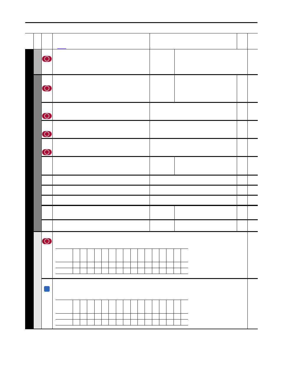
[Decel Mask]
Controls which adapters can select the deceleration ramp rate (Pars 662
[Decel Time 1] and 32 [Decel Time 2]) of the drive.
32,
662
Da
ta
Li
n
ks
610
611
[Data In A1] – Link A Word 1
[Data In A2] – Link A Word 2
Parameter number whose value will be written from a communications
device data table. The number will not be updated until the drive is
stopped.
See your communications option manual for datalink information.
Default:
Min/Max:
0 (0 = “Disabled”)
0 / 1410
16-bit
Int
612
613
[Data In B1] – Link B Word 1
[Data In B2] – Link B Word 2
See [Data In A1] – Link A Word 1.
16-bit
Int
614
615
[Data In C1] – Link C Word 1
[Data In C2] – Link C Word 2
See [Data In A1] – Link A Word 1.
16-bit
Int
616
617
[Data In D1] – Link D Word 1
[Data In D2] – Link D Word 2
See [Data In A1] – Link A Word 1.
16-bit
Int
618
619
[Data Out A1] – Link A Word 1
[Data Out A2] – Link A Word 2
Parameter number whose value will be written to a communications device
data table.
Default:
Min/Max:
0 (0 = “Disabled”)
0 / 1410
16-bit
Int
620
621
[Data Out B1] – Link B Word 1
[Data Out B2] – Link B Word 2
See [Data Out A1] – Link A Word 1.
16-bit
Int
622
623
[Data Out C1] – Link C Word 1
[Data Out C2] – Link C Word 2
See [Data Out A1] – Link A Word 1.
16-bit
Int
624
625
[Data Out D1] – Link D Word 1
[Data Out D2] – Link D Word 2
See [Data Out A1] – Link A Word 1.
16-bit
Int
1319 [Data In Val Sel]
Selects the Datalink parameter register to display in Par 1320 [Data In Sel
Data].
Default:
Min/Max:
610
610 / 617
16-bit
Int
1320
1320 [Data In SelData]
Displays the value selected in Par 1319 [Data In Val Sel].
Default:
Min/Max:
Read Only
0 / 2
31
32-bit
Int
1319
Se
cu
ri
ty
591
[Logic Mask]
Determines which ports can control the drive. If the bit for a port is set to “0,” the port will have no control functions except for stop. 0 = Control Masked, 1
= Control Permitted, x = Reserved.
1376 [Logic Mask Act]
Indicates the status of the logic mask for the DPI ports. When bit 15 is set, network security is
controlling the logic mask instead of Par 591 [Logic Mask]. 0 = Control Masked, 1 = Control
Permitted, x = Reserved.
Read Only
591
Fil
e
Gr
oup
No
.
Parameter Name & Description
See
page 114
for symbol descriptions
Values
Da
ta
T
yp
e
Rela
ted
Options
Re
ser
ve
d
Re
ser
ve
d
Re
ser
ve
d
Re
ser
ve
d
Re
ser
ve
d
Re
ser
ve
d
Re
ser
ve
d
Re
ser
ve
d
Re
ser
ve
d
Re
ser
ve
d
DP
I P
or
t 5
DP
I P
or
t 4
DP
I P
or
t 3
DP
I P
or
t 2
DP
I P
or
t 1
D
igital In
Default
x
x
x
x
x
x
x
x
x
x
1
1
1
1
1
1
Bit
15
14
13
12
11
10
9
8
7
6
5
4
3
2
1
0
A
Options
Se
cur
ity
Re
ser
ve
d
Re
ser
ve
d
Re
ser
ve
d
Re
ser
ve
d
Re
ser
ve
d
Re
ser
ve
d
Re
ser
ve
d
Re
ser
ve
d
Re
ser
ve
d
DP
I P
or
t 5
DP
I P
or
t 4
DP
I P
or
t 3
DP
I P
or
t 2
DP
I P
or
t 1
Digital In
Default
0
x
x
x
x
x
x
x
x
x
1
1
1
1
1
1
Bit
15
14
13
12
11
10
9
8
7
6
5
4
3
2
1
0