Rockwell Automation 23P PowerFlex Digital DC Drive User Manual
Page 202
202
Rockwell Automation Publication 20P-UM001K-EN-P - July 2014
Chapter 3
Programming and Parameters
INPUT / OUT
P
UT
D
igi
tal O
utput
s
1392
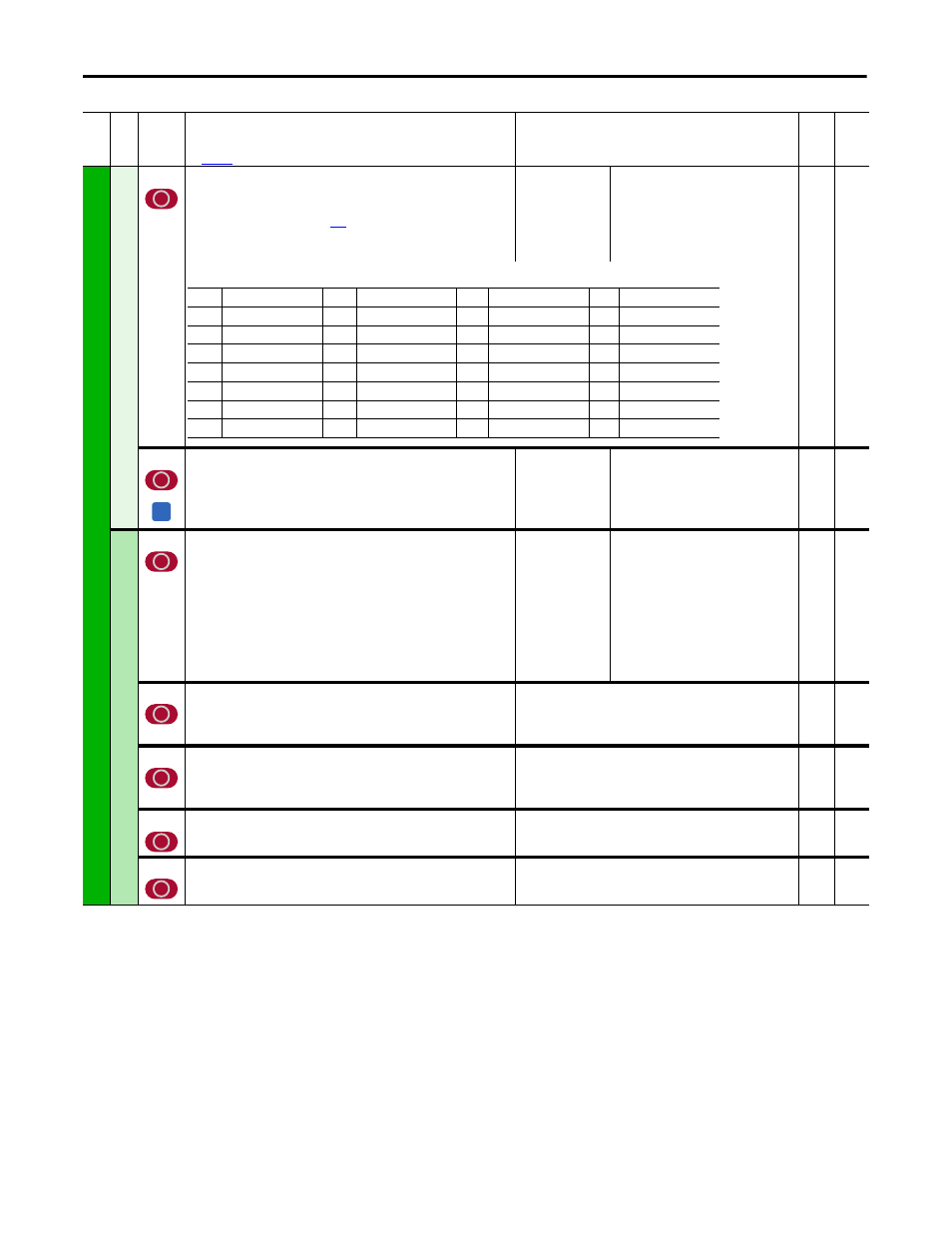
[Relay Out 1 Sel]
Selects the source of the value that drives the N.O. relay between the
terminals 35 and 36.
See “Option Definitions” on page
.
Notes: Option 16 “Encoder Err” was changed for firmware version v5.002.
Options 30 and 31 were added for firmware version v6.001.
Default:
25 =
“Contactor”
16-bit
Int
Options:
1393
[Inversion Relay1]
Inverts the signal for Relay Output 1.
Default:
Options:
0 =
0 =
1 =
“Disabled”
“Disabled”
“Enabled”
16-bit
Int
DPI Inputs
1323
[DPI P1 Select]
Selects the destination of the reference value from DPI Port 1 (HIM on drive
cover, when installed).
Default:
Options:
0 =
0 =
1 =
2 =
3 =
4 =
5 =
6 =
7 =
8 =
“OFF”
”OFF”
“Speed Ref A” (Par 44)
“Speed Ref B” (Par 48)
“Trim Ramp” (Par 42)
“Trim Speed” (Par 43)
“Torque Ref” (Par 39)
“Trim Torque” (Par 40)
“Pos Cur Lim” (Par 8)
“Neg Cur Lim” (Par 9)
16-bit
Int
1324
[DPI P2 Select]
Selects the destination of the reference value from DPI Port 2 (handheld,
remote, and external communication [20-XCOMM-DC-BASE] option, when
installed).
See Par 1323 [DPI P1 Select].
16-bit
Int
1325
[DPI P3 Select]
Selects the destination of the reference value from DPI Port 3 (handheld,
remote, and external communication [20-XCOMM-DC-BASE] option, when
installed).
See Par 1323 [DPI P1 Select].
16-bit
Int
1326
[DPI P4 Select]
Selects the destination of the reference value from DPI Port 4.
See Par 1323 [DPI P1 Select].
16-bit
Int
1327
[DPI P5 Select]
Selects the destination of the reference value from DPI Port 5
(communications adapter, when installed).
See Par 1323 [DPI P1 Select].
16-bit
Int
Fil
e
Gr
oup
No
.
Parameter Name & Description
See
page 114
for symbol descriptions
Values
Da
ta
T
yp
e
Rela
ted
0 =
“Not Used” (Off)
8 =
“Spd Limited”
16 = “Spd Fdbk Err”
24 = “ContactDB”
1 =
“Spd Zero Thr”
9 =
“Fault”
17 = “Diam Calc”
25 = “Contactor”
2 =
“Spd Thresh”
10 = “Power Loss”
18 = “Input1 Cmp”
26 = “Alarm”
3 =
“At Speed”
11 =
“UserDefinedA”
19 = “Diam Reached”
27 = “Running”
4 =
“CurrentLimit”
12 =
“UserDefinedB”
20 = “Speed Match”
28 = “Jogging”
5 =
“Ready”
13 = “Stop Control”
21 = “Accelerating”
29 = “Active”
6 =
“Ramp Pos”
14 = “Field Loss”
22 = “Decelerating”
30 = “Brake Slip”
7 =
“Ramp Neg”
15 =
“Spd Fbk Loss”
23 = “Brake Cmd”
31 = “TP Brake Cmd”
A