Rockwell Automation 23P PowerFlex Digital DC Drive User Manual
Page 129
Rockwell Automation Publication 20P-UM001K-EN-P - July 2014
129
Programming and Parameters
Chapter 3
MO
TO
R C
O
NT
ROL
Mo
tor D
at
a
333
[MtrOvrld Factor]
Sets the derating factor for motor overload. The derating begins when the
motor speed is below the value set in Par 334 [MtrOvrld Speed]. The motor
overload level is determined by Par 376 [MtrOvrld Type] (“StandardDuty” is
150% of Par 179 [Nom Mtr Arm Amps] for 60 sec. or 200% for 3 sec.,
“HeavyDuty” is 200% for 60 sec.) and is linearly decreased from its maximum
to the value of the motor overload factor at zero speed (zero speed is defined
by Par 107 [Zero Speed Level]). This parameter can be used to lower the level
of current that will cause the motor overload function to trip based on motor
speed (The trip action is determined by Par 479 [MtrOvrld Flt Cfg]). For
example, a value of 70% implies continuous operation up to 100% of motor
nameplate current when operating above the value of Par 334 [MtrOvrld
Speed] and only 70% (1.00 * 70%) of motor nameplate current when
operating at zero speed. Setting this parameter to 100% disables the motor
overload derating function so the standard motor overload function is always
active. Note: This parameter was added for firmware version 6.001.
Default:
Min/Max:
Units:
70
20 / 100
%
16-bit
Int
334
[MtrOvrld Speed]
Sets the motor speed (as a percentage of Par 45 [Max Ref Speed]) where the
derating factor (Par 333 [MtrOvrld Factor]) for motor overload capacity
begins. The motor overload capacity is linearly reduced when operating
below [MtrOvrld Speed]. This is to account for the reduced self-cooling
capability of typical motors operating at slower speeds. For motors with low
speed cooling capacity (for example, blower cooling), reduce this setting to
take full advantage of the motor being used. Setting this parameter to 0%
disables the motor overload derating function so the standard overload
function is independent of motor speed. Note: This parameter was added for
firmware version 6.001.
Default:
Min/Max:
Units:
0
0 / 100
%
16-bit
Int
374
[Drv Fld Brdg Cur]
Drive rated field bridge current (I
dFN
). The value in this parameter must be set
equal to the value chosen with DIP switch S14 on the control board (see
for DIP switch configuration). Leave set to the default
value for permanent magnet motor applications.
Default:
Min/Max:
Units:
1.00
0.50 / 80.00
A
Real
376
[MtrOvrld Type]
Allows selection of the type of motor overload calculation based on Par 179
[Motor Arm Amps].
• StandardDuty = 150% load for 1 minute or 200% load for 3 seconds
before a motor overload condition is indicated.
• HeavyDuty = 200% load for 1 minute before a motor overload condition
is indicated (250% for 30 sec). This selection requires that the drive be
oversized relative to the motor to be able to provide the necessary current
without faulting from a “Drive Overload” (F64).
Note: This parameter was added for firmware version 3.001.
Default:
Options:
0 =
0 =
1 =
“StandardDuty”
“StandardDuty”
“HeavyDuty”
16-bit
Int
179,
479,
1290
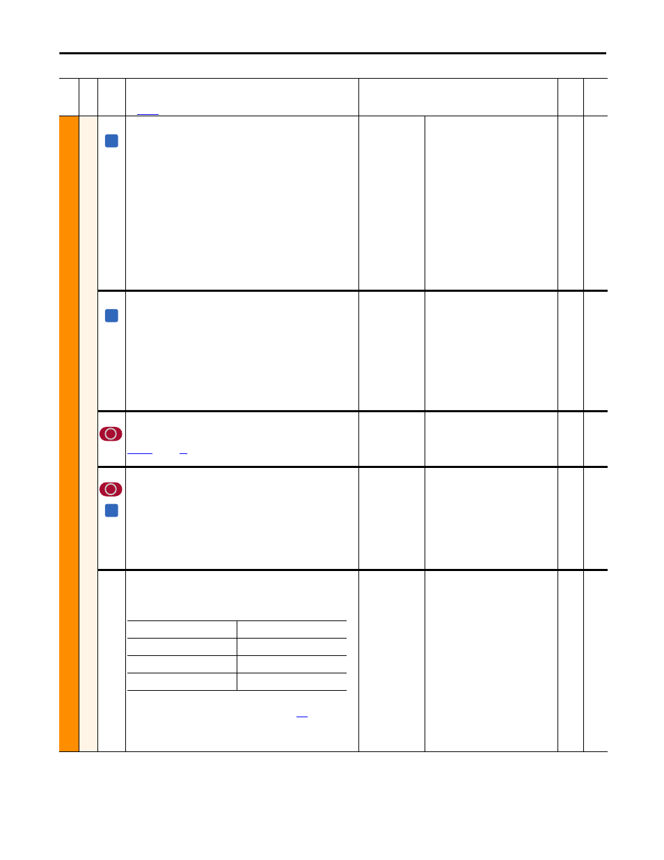
464
[SAR Volts Scale]
Scales the following parameters so that they show actual voltage values
rather than drive calculated values when in Standalone Regulator (SAR)
mode:
Notes: This parameter was added for firmware version 4.001. See Appendix H
PowerFlex DC Standalone Regulator Installation on page
for more
information.
Important: When the drive is not in SAR mode, this parameter is clamped to
the default value (1.0).
Default:
Min/Max:
1.0
0.5 / 10.0
Real
Fil
e
Gr
oup
No
.
Parameter Name & Description
See
page 114
for symbol descriptions
Values
Da
ta
T
yp
e
Rela
ted
A
A
A
175 [Motor Rated Volt]
495 [Arm Volt Kp Base]
233 [Output Voltage]
496 [Arm Volt Ki Base]
466 [AC Line Voltage]
1052 [Output Power]
481 [Undervolt Thresh]
1374 [Fault Voltage]