Rockwell Automation 23P PowerFlex Digital DC Drive User Manual
Page 179
Rockwell Automation Publication 20P-UM001K-EN-P - July 2014
179
Programming and Parameters
Chapter 3
UTILIT
Y
Diagno
st
ic
s
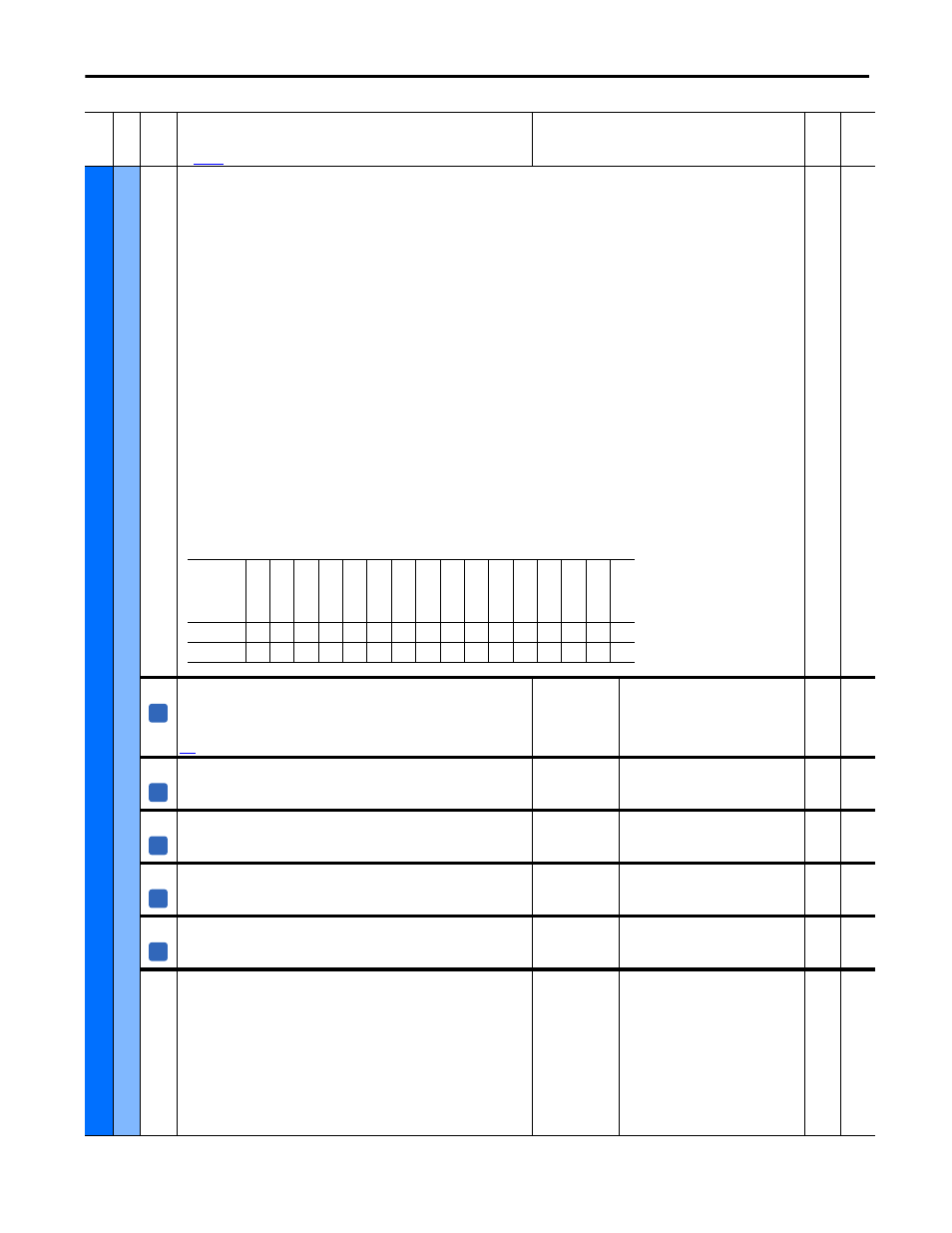
1330 [Spd Ref Sel Sts]
Status of the speed reference selections.
• Bit 0 “Ref A Auto” - When set (= 1), the value of the speed reference is Par 44 [Speed Ref A] and the source in Par 1329 [Speed Ref Source] (Par
1328 [Drive Logic Rslt], bits 12…14 = 001).
• Bit 1 “Ref B Auto” - When set, the value of the speed reference is Par 49 [Speed Ref B] and the source in Par 1329 [Speed Ref Source] (Par 1328
[Drive Logic Rslt], bits 12…14 = 010).
• Bit 2 “Min Spd Lim” - When set, the speed reference value is clamped to the value of Par 5 [Min Speed Fwd] or 6 [Min Speed Rev], based on
direction.
• Bit 3 “Max Spd Lim” - When set, the speed reference value is clamped to the value of Par 3 [Max Speed Fwd] or 4 [Max Speed Rev], based on
direction.
• Bit 4 “MicroPsnMult” - When set, the selected speed reference is multiplied by the value of Par 1112 [MicroPsnScalePct].
• Bit 5 “Trim Ramp” - When set, the speed reference is offset (non-zero) by the value in Par 42 [Trim Ramp].
• Bit 6”Trim Speed” - When set, the speed reference is offset (non-zero) by the value in Par 43 [Trim Speed].
• Bit 7 “Preset Auto” - When set, the speed reference is the “Preset Spd x Auto” source selected in Par 1328 [Drive Logic Rslt],
bits 12…14 = 011…111.
• Bit 8 “Manual Ref” - When set, the speed reference is the manual reference selected in Par 1328 [Drive Logic Rslt], bits 12…14 = 000.
• Bit 9 “Scaled Ref” - When set, the speed reference is the result of the scale block configured to write to the parameter specified in
Par 1329 [Speed Ref Source]. Note that if no speed reference is selected (Par 1329 [Speed Ref Source] = 0), this bit will be set (=1) if any of the
Scale Block input parameters are at their default value of 0.
• Bit 10 “Bipolar Ref” - When set, Par 1322 [Direction Mode] = 1 “Bipolar” and the sign of the reference determines motor rotation direction.
• Bit 11 “Rev Disable” - When set, Par 1322 [Direction Mode] = 2 “Rev Disable” and negative speed reference values are clamped to zero.
• Bit 12 “Unipolar Ref” - When set, Par 1322 [Direction Mode] = 0 “Unipolar” and the sign of the speed reference (and motor rotation direction)
is selected by Par 1328 [Drive Logic Rslt], bit 4 “Forward” or bit 5 “Reverse.”
• Bit 13 “Decel Lmt Sw” - When set, torque proving logic detected an active deceleration limit switch and selected Par 154 [Preset Speed 1] for
the reference.
• Bit 14 “End Lim Sw” - When set, torque proving logic detected an active end limit switch and selected zero speed for the reference.
Note: This parameter was added for firmware version 6.001.
16-bit
Int
1381 [TestPoint Sel]
Selects the function whose value is displayed in [TestPoint Val]. These are internal
values that are not accessible through any other parameters. Typically, these are
internal drive variables and registers. See Testpoint Codes and Functions on page
for more information.
Default:
Min/Max:
566
566 / 574
16-bit
Int
1382 [TestPoint Data]
The present value of the function selected in Par 1381 [Testpoint Sel].
Default:
Min/Max:
Read Only
-2
31 /
2
31
- 1
16-bit
Int
1384 [TaskLoad 1 ms]
The load percentage of the 1 ms task in the firmware.
Default:
Min/Max:
Read Only
0.00 / 100.00
Real
1385 [TaskLoad 2 ms]
The load percentage of the 2 ms task in the firmware.
Default:
Min/Max:
Read Only
0.00 / 100.00
Real
1386 [TaskLoad 8 ms]
The load percentage of the 8 ms task in the firmware.
Default:
Min/Max:
Read Only
0.00 / 100.00
Real
1402 [Last Stop Source]
Displays the source that initiated the most recent stop sequence.
Default:
Options:
0 =
1 - 5 =
6 =
7 =
8 =
9 =
10 =
11 =
12 =
13 =
Read Only
“Pwr Removed”
“DPI Port 1-5”
“Reserved”
“Digital In”
“Fault”
“Not Enabled”
“Reserved”
“Jog”
“Selftune”
“Reserved”
16-bit
Int
Fil
e
Gr
oup
No
.
Parameter Name & Description
See
page 114
for symbol descriptions
Values
Da
ta
T
yp
e
Rela
ted
Options
Re
se
rv
ed
End Lim
Sw
De
ce
l L
m
t S
w
Un
ipo
la
r R
ef
Re
v D
is
able
Bip
ol
ar
Re
f
Scal
e R
ef
Manual Ref
Pr
es
et A
ut
o
Tr
im
S
peed
Tr
im
R
am
p
Micr
oP
sn
Mul
t
Max Spd
Lim
Min Sp
d
Lim
Re
f B
Aut
o
Re
f A
Au
to
Default
x
0
0
0
0
0
0
0
0
0
0
0
0
0
0
0
Bit
15
14
13
12
11
10
9
8
7
6
5
4
3
2
1
0
A
A
A
A
A