Figure 18, Figure 19, Xcd s1 – Rockwell Automation 23P PowerFlex Digital DC Drive User Manual
Page 38
38
Rockwell Automation Publication 20P-UM001K-EN-P - July 2014
Chapter 1
Installation and Wiring
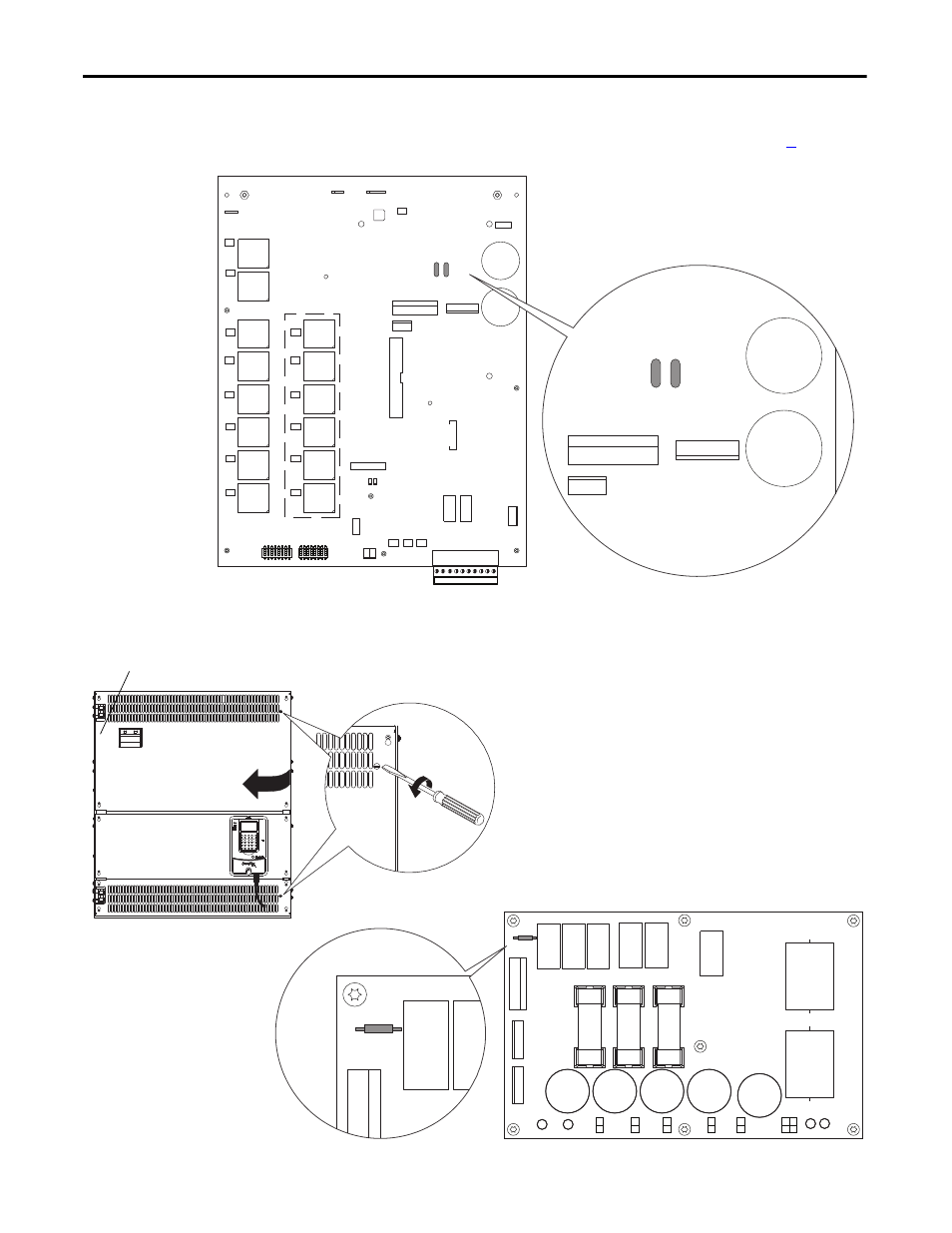
Figure 18 - Frame D Pulse Transformer Circuit Board S1 Jumper Location
Figure 19 - Frame D Overvoltage Clipping Circuit Board S1 Jumper Location
XUV
XSW
XSW1
XCD_IO
XUVW
XCD
XR
XSPF
S3
78 79 35 36 75 76 81 82 U2 V2
X4 X5 X6
XTA
TR2
TR1
T1
T4
T2
T5
T3
T6
PE
XP1
XP2
KG1
KG4
KG2
KG5
KG3
KG6
KG01
KG04
KG02
KG05
KG03
KG06
T01
T04
T02
T05
T03
T06
XCT
S4
XY
X3
C122
C121
XCD_IO
XUVW
C122
C121
Note: The pulse transformer circuit board is behind the top and bottom control panel covers. See page
for
instructions on removing the covers from the drive.
XCD
X1UVW1
XUVW
F31
F21
F11
S1
XCD
S1
90°
Note: The overvoltage clipping circuit board is behind the control panel on the upper left side of
the drive chassis. See illustration below, left for instructions on opening the control panel.
Overvoltage clipping board
location inside drive
1. Disconnect the DPI cable from the HIM (if present).
2. Insert a flathead screwdriver into the holes in the right side of the protective
covers on the drive and turn the latch 90° counter-clockwise.
3. Open the control panel to the left.