Figure 22, Po we rf le x dc drive – Rockwell Automation 23P PowerFlex Digital DC Drive User Manual
Page 48
48
Rockwell Automation Publication 20P-UM001K-EN-P - July 2014
Chapter 1
Installation and Wiring
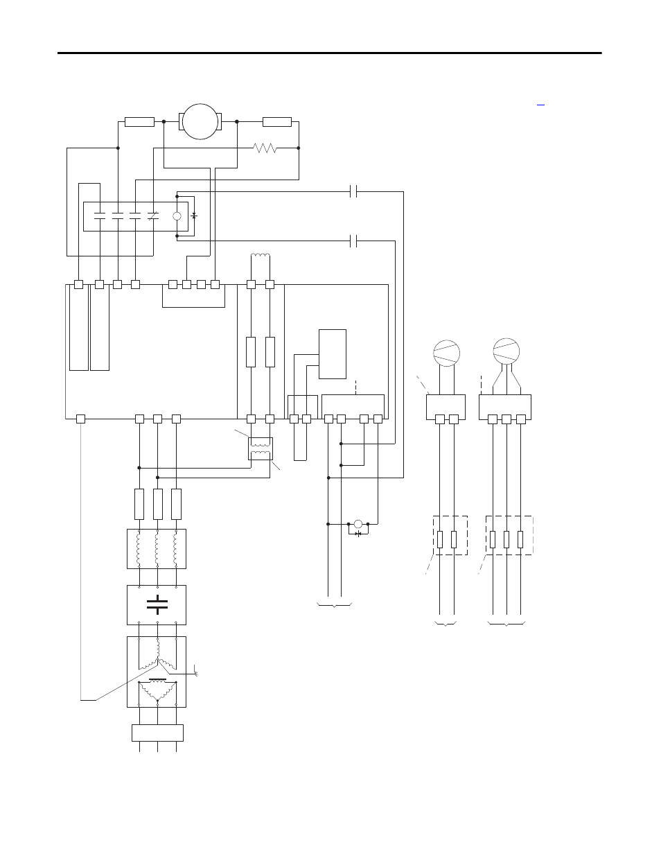
Figure 22 - Power Wiring with DC Output/Dynamic Braking Contactor and a Dynamic Brake
C
D
Po
we
rF
le
x DC
Drive
36
(9)
34
(4)
(on I/O TB4)
19
(5)
(+2
4V - on I/O TB2)
Cont
rol
Bo
ar
d P/
S
U2
V2
F2
35
(9)
U
V
W
U1
V1
C1
D1
F1
FS1
(3)
FS1
(3)
FU1
FV1
Field Power Terminal Block
Control Power / Relay Ouputs
Terminal Block
A1
A2
Armature Volt.
Fdbk. Term. Blk.
1A1
1A2
Line Reactor
(2)
SB
(1)
SA
(1)
Aux
(N
.O
. R
el
ay
)
M1 DC
Cn
tc
tr
13
14
L1
L2
L3
A1
T1
T2
T3
A2
M
A1
A2
FS2
(6)
FS2
(6)
DB
Res.
(8)
FS1
(3)
Isolation
Transformer
(2)
Safety Ground
PE
AC Input
Voltage
460 VAC
Max. or
230 VAC
Min.
(11)
3 P
has
e
AC lin
e
L1
L2
L3
Lockable
Installation
Disconnect
11
5V or 230V AC
Input Source
(1, 12)
EMC Filter
(if used)
K1
(14)
K1
(14)
K1
(14)
Fan Power Terminal Block - Series B ,Frame D Drives Only
(10)
400...460V AC
Input Source
(12)
See footnote
(13)
FU
FU
FU
U3
V3
W3
Fan Power Terminal Block - Frame C and Series A, Frame D Drives Only
(10)
230V AC
Input Source
(12)
See footnote
(13)
FU
FU
U3
V3
See Power Wiring Diagrams Notes on page
for footnotes.