Application example: flying saw – Lenze PLC Designer ApplicationTemplate (PLC Designer R3-x) User Manual
Page 157
Lenze · ApplicationTemplate · 1.3 EN - 04/2013
157
Application example: Flying saw
Creating and integrating machine modules
_ _ _ _ _ _ _ _ _ _ _ _ _ _ _ _ _ _ _ _ _ _ _ _ _ _ _ _ _ _ _ _ _ _ _ _ _ _ _ _ _ _ _ _ _ _ _ _ _ _ _ _ _ _ _ _ _ _ _ _ _ _ _ _
13.3.2
Integrating machine modules in the machine structure tree
The machine modules previously created in the device tree must be integrated in the machine
structure tree (MMT) to make the individual subfunctions of the machine structure executable in
the ApplicationTemplate.
How to proceed:
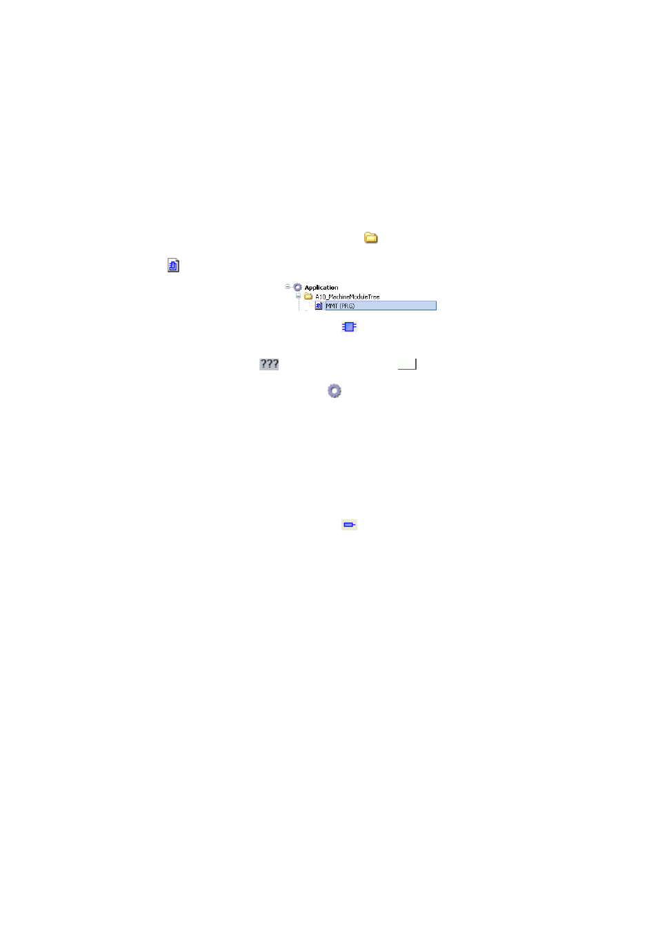
Integrating a machine module in the MMT
1. Double-click and open in the device tree:
A10_MachineModuleTree
2.
Double-click MMT (PRG).
3. In the Tools dialog window, click the
Block button.
• Create the new FB via drag-and-drop.
• Double-click the
area of the FB. Click the
button.
Use the Input assistance from the
Application element...
• ...to assign the MFB_Infeed FB:
Application\A70_MachineModuleSources\MM_B01_Infeed
• ...to assign the MM_Dcl.B01_Infeed instance:
Application\A55_VarLists\MM_Dcl
Note: Go to the Input assistant and select the ; Insert with namespace prefix when
assigning the instance name.
Addressing of the machine modules in the MMT
4. In the Tools dialog window, click the
Input button.
• Add the new input at MM_Address.
• Assign the relative address (example: 1).
Steps 3 and 4 must be executed for all machine modules M 2...M 6. The modules must be
created according to the previously determined tree structure. The representation of the
MMT is rotated by 90 degrees to the left. Every module must be assigned the following
elements:
• The corresponding function block,
• The instance of the module,
• The relative address.