SkyTrak 6036 Service Manual User Manual
Page 82
Boom
3.42
Model 6036 Legacy
Note: ALWAYS use new o-rings when servicing the vehicle.
38. Install new o-rings into the fittings. Lubricate o-rings
with clean hydraulic oil.
39. With optional auxiliary hydraulics: If the inner
boom has been replaced with a new boom, the
auxiliary hydraulic fittings need to be reassembled:
a. Assemble the two bulkhead fittings (Fig. 3 -91, 1)
from the original boom to the bulkhead plate (2)
inside the gooseneck (3). Insert the bulkhead
fittings from the bottom of the bulkhead plate,
and secure in place with the bulkhead fitting nut
(4) on the top side. Tighten securely.
b. Assemble the male nipple (Fig. 3-91, 5) and dust
cap (6) to the right side swivel connector fitting.
Tighten the swivel connector and male nipple
securely. Assemble the dust cap onto the male
nipple.
c. Assemble the female coupler (Fig. 3-91, 7) and
dust plug (8) to the left side swivel connector
fitting. tighten the swivel connector and female
coupler securely. Insert the dust plug into the
female coupler.
d. Assemble the left auxiliary hydraulic hose
(Fig. 3-91, 9) labeled “Female Coupler” from
inside the gooseneck to the female coupler
bulkhead fitting. Tighten securely.
e. Assemble the right auxiliary hydraulic hose
(Fig. 3-91, 10) labeled “Male Nipple” from inside
the gooseneck to the male nipple bulkhead
fitting. Tighten securely.
Figure 3-91 Install the Auxiliary
Hydraulic Coupler and Nipple
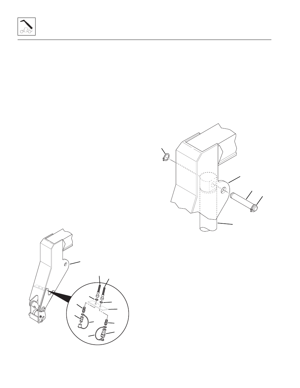
40. Use a hoist and slings to position the attachment tilt
cylinder (Fig. 3-92, 1) inside the gooseneck (2). Be
sure that the attachment tilt cylinder is positioned
with the tube for the rod end positioned inside the
gooseneck.
41. Coat the base end pivot pin (Fig. 3-92, 3) with anti-
seize compound. Align the hole in the cylinder base
end with the mounting holes in the gooseneck, and
insert the pivot pin through the gooseneck. Secure
the pivot pin to the gooseneck with the two retaining
rings (4). Be sure the retaining rings are seated
squarely in the grooves on the pivot pin.
Figure 3-92 Install the Attachment Tilt
Cylinder Base End Pivot Pin
42. Install the quick attach on the gooseneck. (Refer to
Section 3.4.4, “Quick Attach Installation.”)
43. Connect the attachment tilt hoses from the rear of
the gooseneck to the fittings on the base end of the
attachment tilt cylinder. Assemble the left side hose
(Fig. 3-93, 1) labeled as “Retract” to the retract port
(upper) fitting (2) on the base end of the attachment
tilt cylinder. Index the elbow end of the hose to
remove any undo tension and tighten the elbow
completely to the fitting on the cylinder.
44. Connect the right side hose (Fig. 3-93, 3) labeled as
“Extend” to the extend port (lower) fitting (4) on the
base end of the attachment tilt cylinder. Index the
elbow end of the hose to remove any undo tension
and tighten the elbow completely to the fitting on the
cylinder.
MA6410
2
1
3
1
4
4
5
6
7
8
10
9
MA6450
1
2
3
4
4