Warning – SkyTrak 6036 Service Manual User Manual
Page 133
4.29
Model 6036 Legacy
Cab and Covers
4.6
CAB INSTALLATION
1. Block all four wheels to help prevent the vehicle from
moving. Assure that there is sufficient overhead and
side clearance for cab installation.
2. Attach a clevis (Fig. 4-48, 1 and 2) to each of the
cab lifting brackets. Route a sling (3) with a minimum
lifting capacity of 2,000 lbs. (907 kg.) through the
clevis’ to a hoist or overhead crane. Make sure the
sling is centered between the clevis’ to ensure even
lifting.
3. Use a hoist or overhead crane and sling attached to
the cab. Carefully begin to align the cab with the
mounting holes in the frame. Stop and check that
wiring, hydraulic hoses, cables, etc., will not be
pinched or damaged as the cab is positioned.
Readjust the position of the sling as needed to help
balance the cab during installation.
4. Install the two upper capscrews (Fig. 4-48, 4) and two
flat washers (5). Torque the capscrews to 480 lb/ft
(651 Nm).
5. Install the two lower capscrews (Fig. 4-48, 6) and two
flat washers (7). Torque the capscrews to 480 lb/ft
(651 Nm).
6. Route the throttle cable through the opening (Fig. 4-
48, 8) in the bottom of the frame, along the front of
the transmission, along the hydraulic hoses on the
right side of the frame and through the openings in
the frame to the engine compartment.
7. Secure the throttle cable to the hydraulic hoses
using wire ties.
8. Install the throttle cable (Fig. 4 -47, 7) on the throttle
cable bracket (6), using a clamp (5) and two slotted
pan-head screws (4), two lockwashers and two hex
nuts.
Note: ALWAYS replace elastic-lined nuts with new
elastic-lined nuts to help ensure proper fastening.
9. Connect the throttle cable rod end (Fig. 4-47, 2) to
the throttle lever extension bracket (3) using one new
hex-lock elastic nut (1).
10. Vehicles equipped with auxiliary hydraulics only:
Install the auxiliary hydraulics joystick assembly.
(Refer to Section 4.3.7, b. “Auxiliary Hydraulics
Joystick Installation.”)
Note: ALWAYS use new o-rings when servicing the
vehicle.
11. Install new o-rings into the fittings. Lubricate the o-rings
with clean hydraulic oil.
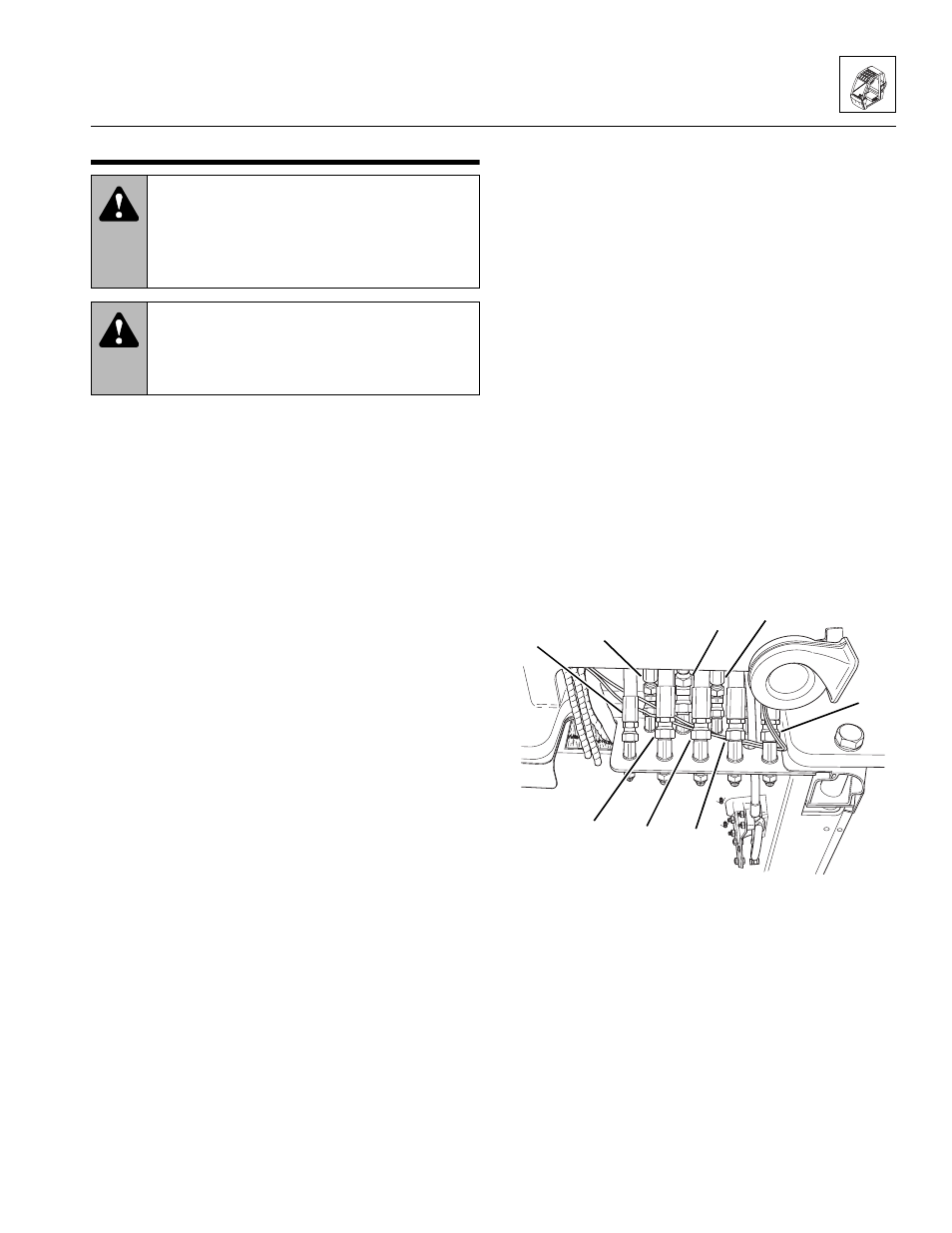
12. Working under the cab, connect the hydraulic hoses
(Fig. 4 -49, 1-8) at the cab fittings.
Figure 4- 49 Connect Hydraulic Hoses
WARNING:
Wear protective footwear
with reinforced toe caps and slip-resistant
soles. Failure to comply can result in foot injury
from falling objects or other bodily injury from
slipping or falling.
WARNING:
NEVER lift a heavy object
without the help of at least one assistant or a
suitable sling or hoist. Failure to comply can
result in death or serious personal injury.
MA8500
2
1
3
4
5
6
7
8