SkyTrak 6036 Service Manual User Manual
Page 118
Cab and Covers
4.14
Model 6036 Legacy
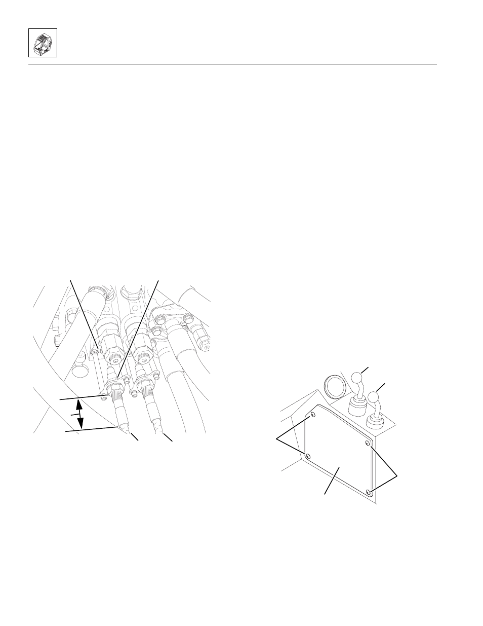
5. Connect the boom lift/lower control cable to the main
control valve assembly:
a. Install the cable in the bracket, and slide the
inner jam nut (Fig. 4-23, 1) over the end of the
boom lift/lower control cable (2). DO NOT tighten
the jam nuts at this time.
b. Connect the end of the cable to the shaft from
the control valve. Secure with an anchor pin and
spring pin (Fig. 4-23, 3).
c. Adjust the jam nuts until the distance (Fig. 4-23, 4)
from the outer jam to the end of the ferrule is the
same as recorded during removal. Tighten the
jam nuts.
6. Repeat Step 5 to install the boom extend/retract
control cable (Fig. 4-23, 5).
Note: If any tie wraps were removed from the joystick
cables beneath the vehicle frame, bundle the cables and
secure with new tie wraps as required to prevent the
cables from contacting any sharp edges or moving parts.
Figure 4-23 Connect the Boom Lift/Lower and
Boom Extend/Retract Control Cables
7. Connect the battery negative (-) cable.
8. Start the engine.
9. Test the boom extend/retract and boom lift/lower
joystick (Fig. 4-24, 1) function:
a. Move the joystick handle rearward, activating the
boom lift function. The boom should RISE.
b. Move the joystick handle forward, activating the
boom lower function. The boom should LOWER.
c. Move the joystick handle to the right, activating
the boom extend function. The boom should
EXTEND.
d. Move the joystick handle to the left, activating the
boom retract function. The boom should
RETRACT.
10. Test the attachment tilt/frame sway joystick (Fig. 4-24,
2) function:
a. Move the joystick handle rearward, activating the
attachment tilt function. The attachment should
TILT DOWN.
b. Move the joystick handle forward, activating the
attachment tilt function. The attachment should
TILT UP.
c. Move the joystick handle to the right, activating
the frame sway function. The boom should frame
SWAY RIGHT.
d. Move the joystick handle to the left, activating the
frame sway function. The boom should frame
SWAY LEFT.
11. Install the console panel (Fig. 4-24, 3) and secure
using four button-head screws (4).
Figure 4- 24 Install the Console Panel
4
MA8480
3
1
2
5
OH2430
4
3
~
4
1
2