Warning – SkyTrak 6036 Service Manual User Manual
Page 340
Hydraulic System
8.124
Model 6036 Legacy
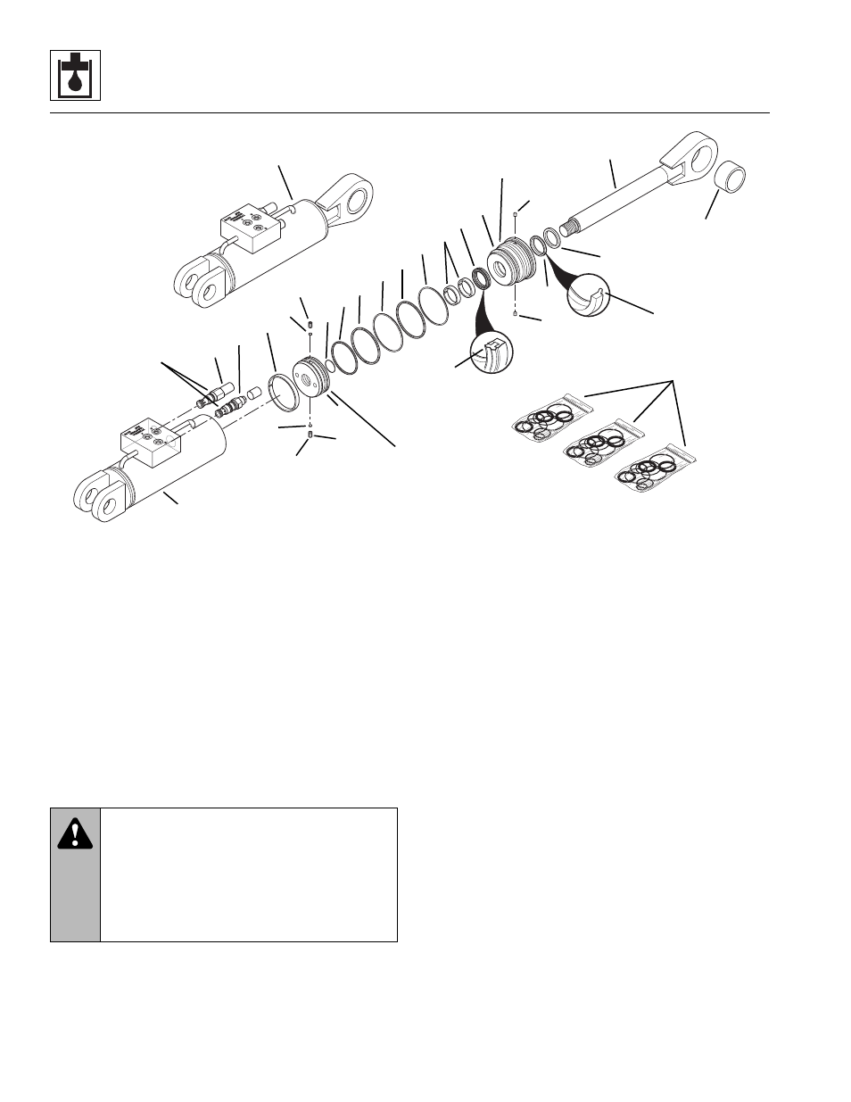
Figure 8- 83 Swing Carriage Cylinder Components (Optional)
b. Swing Carriage Cylinder Disassembly
Note: An additional o-ring may be included at the base
of the cylinder rod. This additional o-ring may be discarded,
as it served only in a temporarily protective role.
1. Clean the swing carriage cylinder (Fig. 8-83, 1) with
a suitable cleaner to remove dirt, debris, grease, etc.
IMPORTANT: Avoid using excess force when clamping
the cylinder in a vise. Apply only enough force to hold the
cylinder securely. Excessive force can damage the
cylinder.
2. Secure the swing carriage cylinder in a soft-jawed
vise or other acceptable holding equipment if possible.
3. Slowly remove the 3000 psi (207 bar) counterbalance
cartridge (Fig. 8-83, 2) and the 2000 psi (138 bar)
direct-acting relief valve (3) from the swing carriage
cylinder.
4. If the self-aligning bearing (Fig. 8-83, 23) requires
replacement, support the rod (4) in a soft-jawed vise
or other suitable holding device. Carefully press the
bearing out of the rod eyelet.
5. Extend the rod (Fig. 8-83, 4) to access the cylinder
base.
IMPORTANT: Protect the finish on the rod at all times.
Damage to the surface of the rod can cause seal failure.
6. Using a pin spanner wrench, unscrew the head
gland (Fig. 8-83, 5) from the cylinder tube (6). The
head gland was originally torqued to 250-300 lb/ft
(339-407 Nm), so a considerable amount of force is
required. Carefully slide the head gland down along
the rod toward the eyelet, away from the tube (6).
IMPORTANT: When sliding the rod and piston assembly
into the tube, prevent the threaded end of the tube from
damaging the piston (Fig. 8-83, 7). Keep the rod centered
within the tube to help prevent binding.
7. Carefully pull the rod (Fig. 8-83, 4) with all
attachments straight out of the tube (6).
8. Fasten the rod end in a soft-jawed vise and put a
padded support below and near the threaded end of
the rod to help prevent damage to the rod.
MT1910
Apply Loctite #242 to
threads and torque to
85-95 lb/ft
(115-124 Nm)
Torque to
35-40 lb/ft
(47-54 Nm)
1
Apply Loctite #271 to
threads and torque to
440-500 lb/ft
(597-678 Nm)
22
4
20
21
14
7
8
9
6
3
2
12
9
8
13
11
10
15
16
17
18
19
5
14
Torque to
250-300 lb/ft
(339-407 Nm)
23
24
25
WARNING:
Significant pressure may be
trapped inside the cylinder. Exercise caution
when removing a counterbalance valve or a
pilot-operated check valve from a cylinder.
Escaping hydraulic fluid under pressure can
penetrate the skin, causing death or serious
injury.