SkyTrak 6036 Service Manual User Manual
Page 427
9.75
Model 6036 Legacy
Electrical System
9.14
CAB HEATER AND FAN (OPTION)
9.14.1
Cab Heater Controls
Note: If the suspect component is found to be within the
heater box, the heater box must be removed as a
complete unit and replaced. For additional information
on the removal and installation of the heater box, refer to
Section 4.4.4, a. “Heater Assembly Removal.”
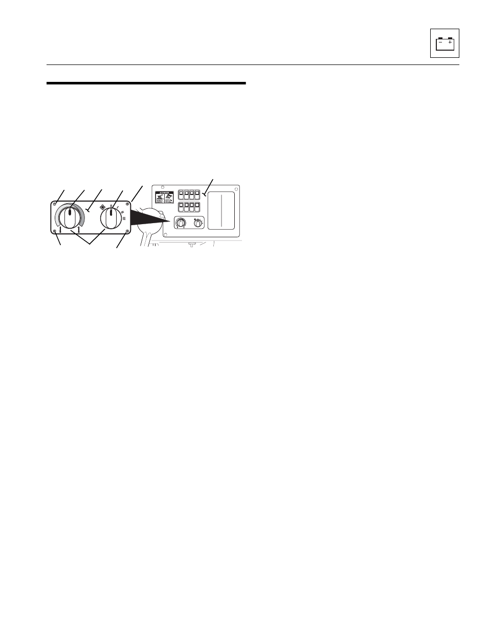
Figure 9-55 Cab Heater and Fan Controls Location
The cab heater controls are located directly below the
switch banks on the right side dash panel. The control
panel (Fig. 9-55, 1) consists of a variable speed fan
control knob (2) and a temperature control knob (3).
a. Cab Heater Controls Removal
Note: After determining which control knob is not
functioning, remove only the suspect control knob. In
order to remove either knob, the cab heater and fan
control panel must be removed from the dash panel.
1. Disconnect the negative (-) battery cable at the
negative battery terminal.
2. Remove the setscrew (Fig. 9-55, 4) from the
variable speed fan control knob (2) or temperature
control knob (3).
3. Remove the screws from the right side control panel
(Fig. 9-55, 9).
4. Remove the screws and backing locknuts (Fig. 9 -55,
5, 6, 7 and 8) from the cab heater and fan control
panel (1).
5. Pull the control panel out from the dash panel, and if
removing variable speed fan control, remove the cab
harness connector.
6. If removing the temperature control knob, disconnect
the cable connector and remove control knob.
7. Remove the hex locknut from the suspect control
shaft.
8. Remove the control from the panel.
b. Disassembly
DO NOT disassemble the cab heater and fan controls.
The controls are not serviceable. Replace controls if
found to be defective.
c. Cleaning and Drying
Without submerging the variable speed fan control, clean
the control with an approved solvent and dry with a clean,
lint-free cloth.
d. Inspection and Replacement
For additional information, refer to Section 9.7.15, “Heat-
er Circuit and Troubleshooting (Option).”
e. Installation and Testing
1. Check that the variable speed fan control (Fig. 9-55,
2) is in the OFF position.
2. If installing the temperature control (Fig. 9 -55, 3),
attach the control cable (not shown) to the back of
the control.
3. Insert the control shaft through the panel, ensuring
that the knob is in the vertical position.
4. Install the hex locknut on the shaft and tighten.
5. Connect the cab harness connector to the variable
speed fan control.
6. Install the screws and backing locknuts (Fig. 9-55, 5,
6, 7 and 8), securing the control panel to the dash
panel.
7. Install the setscrew (Fig. 9-55, 4), securing the knob
to the control.
8. Install the right side control panel screws (Fig. 9-55,
9).
9. Connect negative (-) battery cable at the negative
battery terminal.
MA8700
3
2
4
5
8
7
6
1
9