SkyTrak 6036 Service Manual User Manual
Page 348
Hydraulic System
8.132
Model 6036 Legacy
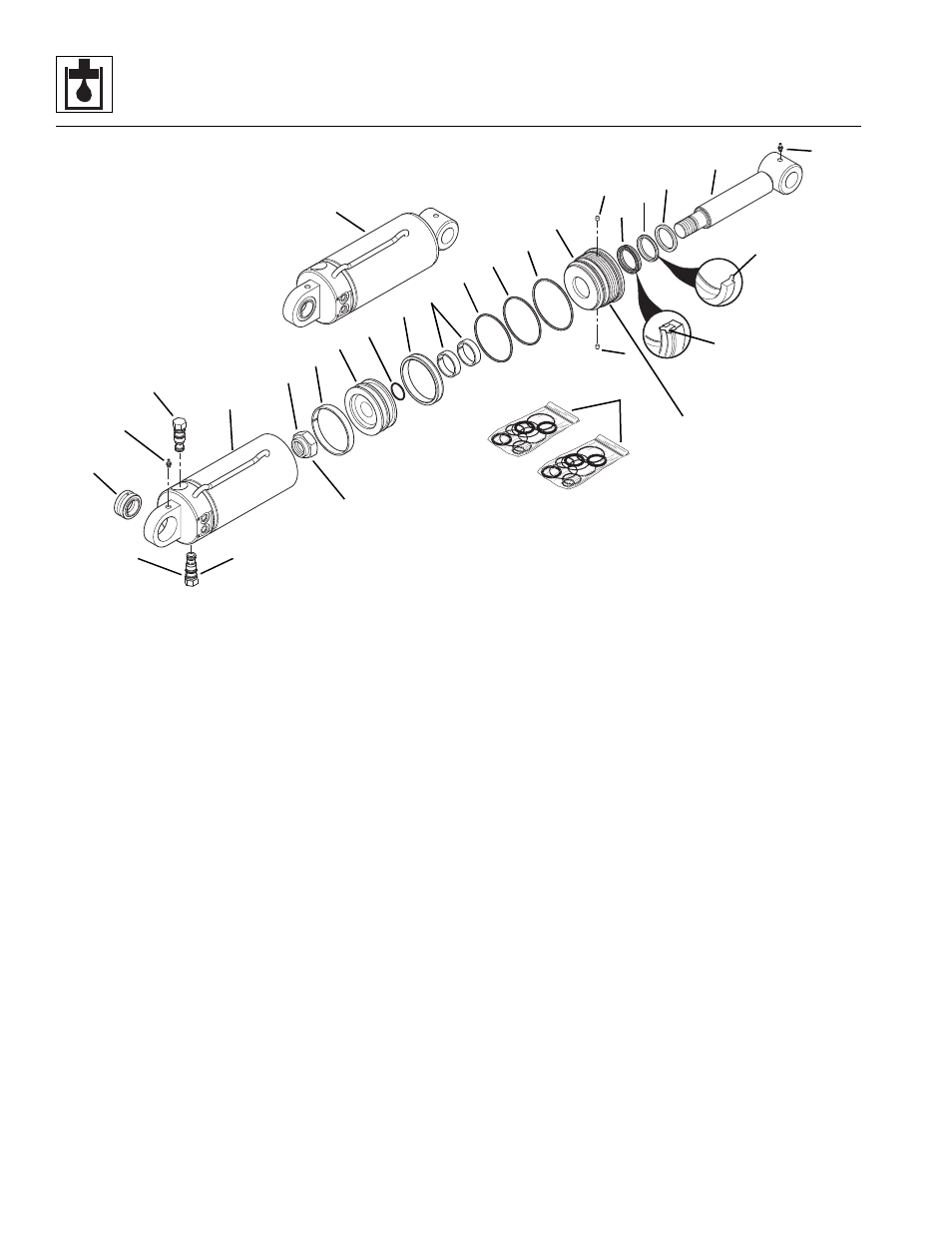
Figure 8-89 Side Tilt Carriage Cylinder Components
e. Side Tilt Carriage Cylinder Assembly
Note: Follow the general assembly instructions in
Section 8.13.3, “General Cylinder Assembly Instructions.”
1. If necessary, press the self-aligning bearings
(Fig. 8-89, 3) into the cylinder tube and rod ends.
The bearings should protrude equally from each side
of the eyelet.
2. Install the precision wearbands (Fig. 8-89, 18) into
the rear of the head gland, and the deep Z-seal (19),
rod wiper (20) and square ring (21) into the front of
the head gland (7). Orient the Z-seal edge (23). The
rod wiper lip (22) should be toward the outer end of
the head gland and the seal lips toward the inner
end of the head gland. Use tools that will not
damage the seals.
3. Install new oiled o-ring (Fig. 8-89, 12), back-up ring
(11) and oiled o-ring (10) on the head gland (7).
4. Fasten the rod end in a soft-jawed vise and put a
padded support below and near the threaded end of
the rod to help prevent damage to the rod.
5. Carefully slide the head gland (Fig. 8-89, 7) onto the
rod (6). If necessary, use a soft hammer to drive the
head gland onto the rod.
6. Install a new small oiled o-ring (Fig. 8-89, 17) inside
the rod end of the piston (8).
7. Install the capped T-seal (Fig. 8-89, 14) and the
precision wearband (13) on the piston (8).
8. Carefully slide the piston (Fig. 8 -89, 8) onto the rod
(6).
9. Apply Loctite Primer “T” and Threadlocker #271
(red) to the threads of the locknut (Fig. 8 -89, 16) in
accordance with Loctite instructions. Thread the
locknut onto the rod (6) and torque to 550-650 lb/ft
(746-881 Nm).
IMPORTANT: Avoid using excess force when clamping
the cylinder in a vise. Apply only enough force to hold the
cylinder securely. Excessive force can damage the
cylinder tube (Fig. 8-89, 4).
10. Fasten the cylinder tube (Fig. 8-89, 4) in a soft-
jawed vise or other acceptable holding equipment.
11. Lubricate the piston (Fig. 8-89, 8), head gland (7)
and the inside of the tube (4) with clean, filtered
hydraulic oil.
12. Apply a compression sleeve or other suitable tool to
the head gland (Fig. 8-89, 7) in order to compress
the o-ring (10), back-up ring (11) and o-ring (12).
MT1920
Torque to
30-35 lb/ft
(41-47 Nm)
6
Apply Loctite #271 to
threads and torque to
550-650 lb/ft
(746-881 Nm)
Torque to
300-400 lb/ft
(407-542 Nm)
1
21
20
19
9
7
12
11
10
18
14
17
8
13
16
4
5
2
3
5
9
15
2
22
23