Warning – SkyTrak 6036 Service Manual User Manual
Page 48
Boom
3.8
Model 6036 Legacy
18. Remove the elastic locknut (Fig. 3-11, 1) and
shoulder bolt (2) holding the two yoke plates (3) to
disconnect the extend chain yoke (4) from the outer
boom. Retain the shoulder bolt and discard the
elastic locknut. Lay the chain assembly flat against
the inner boom.
19. Inspect the yoke plates for wear or distortion. If any
wear or distortion is detected, both plates must be
replaced. If no wear is detected, the plates can
remain assembled to the extend chain clevis’.
Figure 3-11 Disconnect the Extend Chain
Note: If replacing the inner boom assembly with a new
inner boom, the quick attach assembly and the
attachment tilt cylinder should be removed at this time. If
the inner boom is not to be replaced, the quick attach
assembly and attachment tilt cylinder can remain in place.
20. Remove the quick attach assembly. (Refer to Section
3.4.3, “Quick Attach Removal.”)
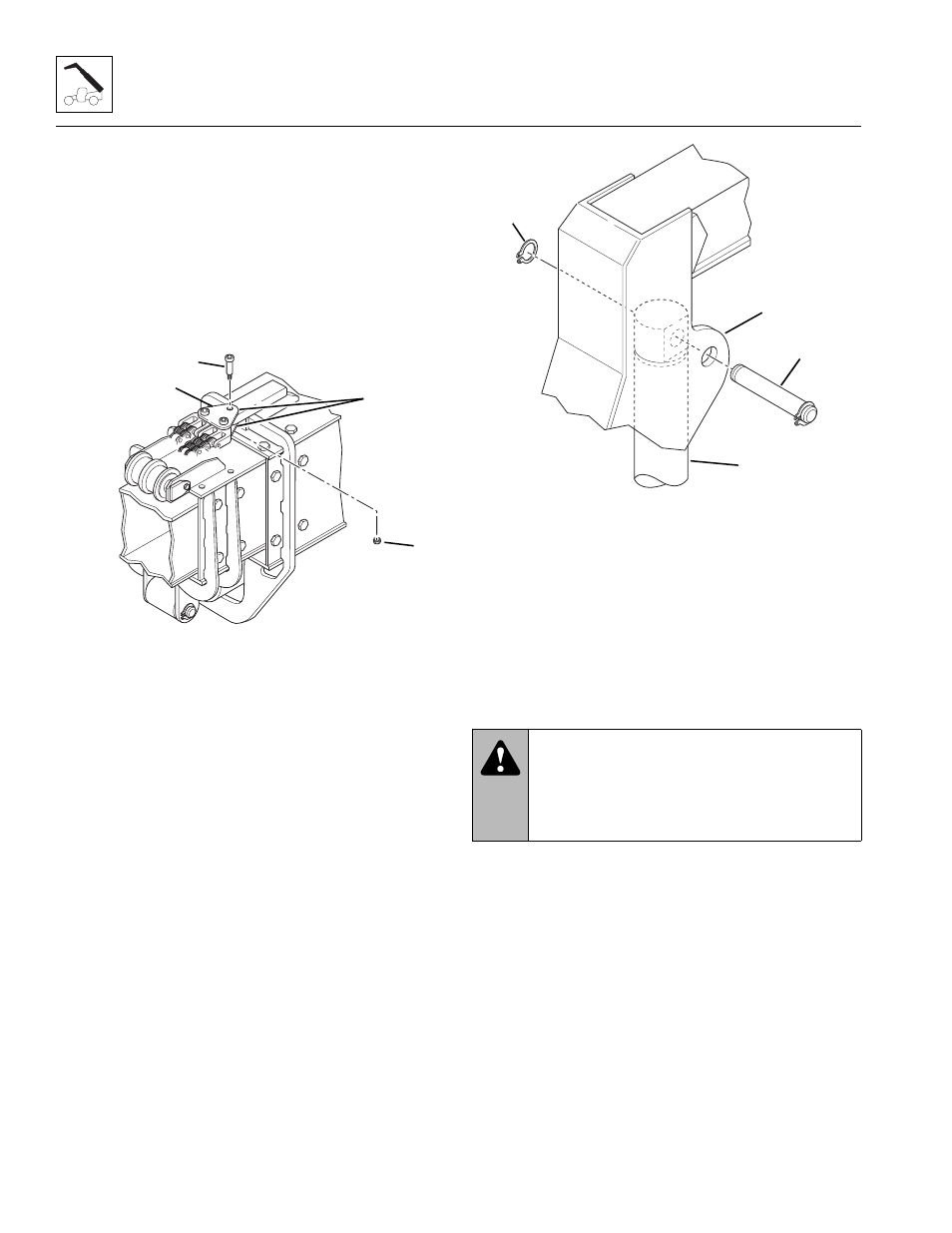
Note: The attachment tilt cylinder is heavy. Use a hoist
and sling to support the attachment tilt cylinder when the
base end pin is removed.
21. Remove the retaining ring (Fig. 3-12, 1) from one
side of the base end pivot pin (2). Save the retaining
ring. Use a brass punch and rawhide hammer to
remove the base end pivot pin from the inner boom
gooseneck (3).
22. Inspect the pin for nicks or surface corrosion. Use
fine emery cloth to fix minor nicks or corrosion. If
damaged and not repairable, the pin must be
replaced.
23. Lower the attachment tilt cylinder (Fig. 3-12, 4) with
the hoist, and remove it from the rear of the
gooseneck. Place the attachment tilt cylinder on a
clean, level surface until installation.
Figure 3-12 Remove Attachment Tilt Cylinder
Note: Use a hoist capable of lifting 5000 lbs (2268 kg)
and two slings to remove the inner boom.
24. Place the slings around the inner boom. Pull the
inner boom straight out of the intermediate boom.
25. Reposition the sling at the approximate center of the
inner boom, and then continue withdrawing the boom
until it clears the vehicle.
26. Carefully lower the inner boom onto suitable
supports to prevent it from tipping over.
27. Inspect the boom and welds. Contact the JLG
Service Department or the local JLG Authorized
Service Center (ASC) if structural damage is
detected.
28. Inspect hoses, hardware, wear pads, mounting
points, chains and other components visible with the
inner boom removed. Replace if damaged.
29. At the rear of the inner boom (Fig. 3-13, 1), remove
the capscrews (2), lockwashers (3) and flat washers
(4) holding the top wear pads (5), spacers (6) and
shims (7) to the top of the inner boom. Label the
wear pads, spacers and shims as “Top Left” and
“Top Right” sides. Save the spacers, shims,
capscrews, lockwashers and wear pad inserts (8).
MA7810
1
3
2
4
WARNING:
NEVER weld or drill the
boom. The structural integrity of the boom will
be impaired if subjected to any repair involving
welding or drilling. Failure to comply can result
in death or serious personal injury.
MA6450
1
2
3
4