Warning – SkyTrak 6036 Service Manual User Manual
Page 285
8.69
Model 6036 Legacy
Hydraulic System
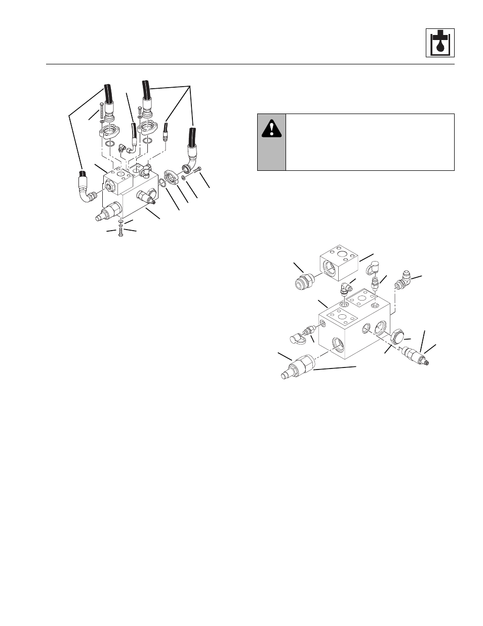
Figure 8- 35 Unloader Valve Removal
b. Unloader Valve Disassembly, Inspection and
Assembly
1. Safely secure the unloader valve (Fig. 8-36, 1) in a
bench vise or by other suitable means.
2. Slowly remove the check valve (Fig. 8-36, 2).
3. Remove the relief valve (Fig. 8-36, 3) and remove
the differential pressure sense valve (4).
4. Remove the diagnostic test nipples (Fig. 8-36, 5)
and remaining fittings (6). Remove the fitting (8) from
the manifold (7).
Figure 8- 36 Unloader Valve Components
5. Clean metal parts with an approved solvent such as
triclorethylene and blow dry.
6. Inspect all sealing surfaces. They must be clean,
smooth and free of damage, and have no indication
of wear. Replace parts if damaged or worn.
Note: ALWAYS replace seals, o-rings, gaskets, etc.,
with new parts to help ensure proper sealing and operation.
Lubricate seals and o-rings with clean hydraulic oil.
7. Install the check valve (Fig. 8 -36, 2) and torque to
80-90 lb/ft (108-122 Nm).
8. Install the relief valve assembly (Fig. 8-36, 3) and
torque to 35-40 lb/ft (47-54 Nm).
9. Install the differential pressure sense valve assembly
(Fig. 8-36, 4) and torque to 80-90 lb/ft (108-122 Nm).
10. Install diagnostic nipples (Fig. 8-36, 5) and fittings (6).
Install the fitting (8) on the manifold (7).
LSG
VG
MA7140
1
9
7
8
2
6
5
4
3
2
10
11
2
WARNING:
Significant pressure may be
trapped inside the valve. Exercise caution
when removing a valve. Escaping hydraulic
fluid under pressure can penetrate the skin,
causing death or serious injury.
LSG
P
T
VG
LS
MA7150
1
2
3
4
Torque to
80-90 lb/ft
(108-122 Nm)
Torque to
35-40 lb/ft
(47-54 Nm)
6
5
5
7
8
6