SkyTrak 6036 Service Manual User Manual
Page 64
Boom
3.24
Model 6036 Legacy
19. Use a hoist and sling to position the slave cylinder
(Fig. 3-54, 1) onto the lower cylinder mount (2)
located on the frame. The cylinder should be
positioned with the port fittings (3) toward the outside.
20. Coat the lower pivot pin (Fig. 3-54, 4) with anti-seize
compound. Insert the pin through the base end of
the slave cylinder. Use a tapered punch to line up
the capscrew hole in the pin with the mounting tabs
on the cylinder. Secure the lower pivot pin in place
with the capscrew (5) and a new 1/2-13 elastic
locknut (6). Tighten the elastic locknut securely.
21. Position the rod end of the slave cylinder (Fig. 3-54, 7)
around the self-aligning bearing on the outer boom.
22. Coat the upper pivot pin (Fig. 3-54, 8) with anti-seize
compound. Insert the pin through the rod end of the
slave cylinder. If necessary, use a rawhide hammer
to install the upper pivot pin. Use a tapered punch to
align the capscrew hole in the pin with the mounting
tabs on the cylinder. Secure the upper pivot pin in
place with the capscrew (9) and a new 1/2-13 elastic
locknut (10). Tighten the elastic locknut securely.
23. Repeat Steps 19-22 to install the other slave cylinder
on the other side of the outer boom.
Figure 3- 54 Install the Slave Cylinder
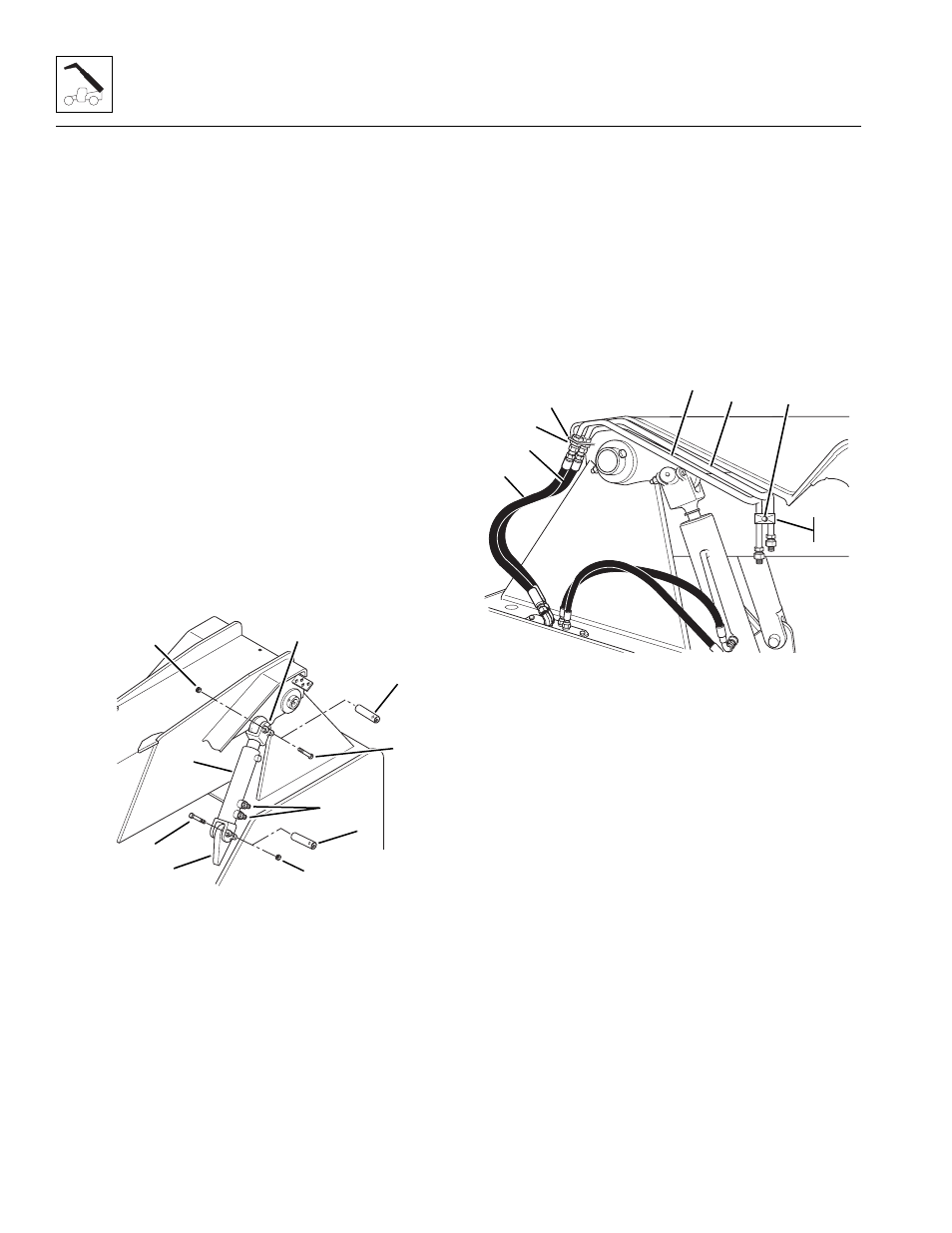
Note: ALWAYS use new o-rings when servicing the
vehicle.
24. Install new o-rings into the fittings. Lubricate o-rings
with clean hydraulic oil.
25. Install the extend (Fig. 3-55, 1) and retract (2) tubes
to the mounting plate (3). Secure the tubes to the
mounting plate with bulkhead nuts (4).
26. Install the tube clamp halves (Fig. 3-55, 5) to the
extend (1) and retract (2) tubes. Place one clamp
half on top of the tubes and one on the underside of
the tubes. Place a clamp cover (6) on the top and
bottom of the clamps. Secure in place with the
5/16-18 x 2" capscrew and flat washer (7). Position
the clamp halves to securely hold the tubes without
putting tension on either tube.
27. Connect the extend (Fig. 3-55, 8) and retract (9)
hoses to the tubes at the mounting plate (3). Tighten
the connections.
Figure 3-55 Install the Extend and Retract Tubes
Note: ALWAYS use new o-rings when servicing the
vehicle.
28. Install new o-rings into the fittings. Lubricate o-rings
with clean hydraulic oil.
29. Remove the plugs and caps from the hoses and
fittings, and loosely connect the extend (Fig. 3-56, 1)
and retract (2) hoses to the extend and retract tubes
(3 and 4).
30. Remove the plugs and caps from the hoses and
fittings, and loosely connect the extend (Fig. 3-56, 1)
and retract (2) hoses to the 90° elbow fittings at the
rear of the extend/retract cylinder (5).
31. Remove any twists from the hoses, and tighten the
connections.
MA6460
1
2
3
6
4
5
7
8
10
9
MA6880
1
2
3
4
7
6
5
8
9