SkyTrak 6036 Service Manual User Manual
Page 363
9.11
Model 6036 Legacy
Electrical System
9.7.3
Probing Electrical Connectors
a. Front Probe
Disconnect the connector and probe the terminals from
the mating side (front) of the connector.
Note: DO NOT insert test equipment probes into any
connector or fuse block terminal. The diameter of the
test probes will deform most terminals. A deformed
terminal can cause a poor connection, which can result
in system failures. Always use a connector test adapter
kit or a flat wire probe adapter kit (usually supplied with a
DMM) when front probing terminals. DO NOT use paper
clips or other substitutes as they can damage terminals
and cause incorrect measurements.
b. Back Probe
DO NOT disconnect the connector and probe the
terminals from the harness side (back) of the connector.
• Back probe connector terminals only when
specifically required in diagnostic procedures.
• DO NOT back probe a sealed connector or a flat
wire connector.
• Back probing can be a source of damage to
connector terminals. Use care in order to avoid
deforming the terminal, either by forcing the test
probe too far into the cavity or by using too large
of a test probe.
• After back probing any connector, inspect for
terminal damage. If terminal damage is
suspected, test for proper terminal contact.
c. Measuring and Testing Voltage
Testing for Voltage Drop
This test checks for voltage being lost along a wire, or
through a connection or switch.
1. Connect the positive lead of a DMM to the end of the
wire (or to one side of the connection or switch)
which is closer to the battery.
2. Connect the negative lead to the other end of the
wire (or the other side of the connection or switch).
3. Operate the circuit.
4. Voltage through the wire should be displayed.
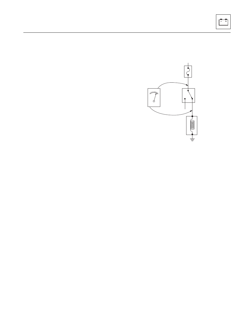
Measuring Voltage Drop
The following test (Fig. 9-8) determines the difference in
voltage potential between two points.
Figure 9-8 Measuring Voltage Drop
1. Set the rotary dial of the DMM to the V (DC) position.
2. Connect the (+) positive lead of the DMM to one
point of the circuit to be tested.
3. Connect the (-) negative lead of the DMM to the
other point of the circuit.
4. Operate the circuit.
5. The DMM displays the difference in voltage between
the two points.
(POWER ON AT ALL TIMES)
(+)
(-)
DMM
SOLENOID
BLK
RED
SWITCH
FUSE
BLOCK
MT0410