SkyTrak 6036 Service Manual User Manual
Page 342
Hydraulic System
8.126
Model 6036 Legacy
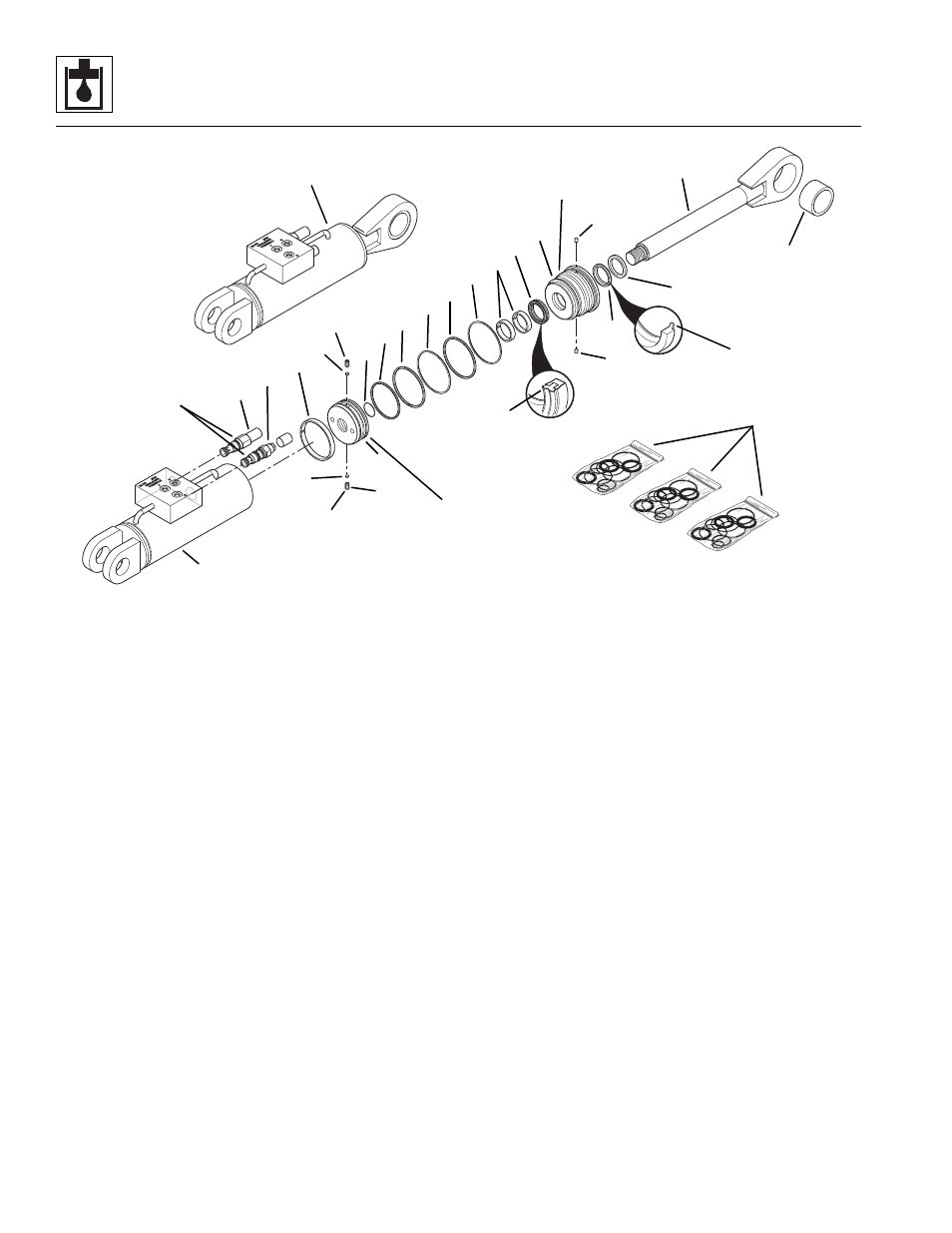
Figure 8- 84 Swing Carriage Cylinder Components (Optional)
5. Install two new locking inserts (Fig. 8-84, 14) into
their holes in the head gland threads.
6. Install a new small oiled o-ring (Fig. 8-84, 13) into
the piston (7).
7. Install a new piston square seal (Fig. 8-84, 10),
square ring (11) and precision wearband (12) onto
the piston (7).
8. Apply Loctite Primer “T” and Threadlocker #271
(red) to the threads of the piston (Fig. 8-84, 7) in
accordance with Loctite instructions. Thread the
piston (7) onto the rod (4) and torque to 440-500 ft/lb
(597-678 Nm).
9. Install two new setscrews (Fig. 8-84, 8) with locking
inserts (9) into their holes in the piston (7). Torque to
85-95 lb/ft (115-124 Nm).
IMPORTANT: Avoid using excess force when clamping
the cylinder in a vise. Apply only enough force to hold the
cylinder securely. Excessive force can damage the
cylinder tube (Fig. 8-84, 6).
10. Place the cylinder tube (Fig. 8-84, 6) in a soft-jawed
vise or other acceptable holding equipment if
possible.
11. Lubricate the piston (Fig. 8-84, 7), head gland (5)
and the inside of the tube (6) with clean, filtered
hydraulic oil.
12. Apply a compression sleeve or other suitable tool to
the head gland (Fig. 8-84, 5) in order to compress
the o-rings (15 and 17).
IMPORTANT: When sliding the rod and piston assembly
in the tube, prevent the threaded end of the tube from
damaging the piston (Fig. 8-84, 7). Keep the rod
centered within the tube to help prevent binding.
13. Carefully insert the rod (Fig. 8-84, 4) with all
attachments straight into the tube (6). Use a pin
spanner wrench to thread the head gland into the
tube. Torque the head gland to 250-300 lb/ft
(339-407 Nm). Remove the compression tool.
14. Using new oiled o-rings, install the counterbalance
valve (Fig. 8-84, 2) and direct-acting relief valve (3).
Lubricate the cartridge and valve with clean, filtered
hydraulic oil. Torque the valves to 35-40 lb/ft
(47-54 Nm).
15. Test the cylinder at low operating pressure (100 psi
or 7 bar). Verify that the piston and rod move freely
in both directions.
16. Increase the operating pressure to the maximum for
the cylinder [3000 psi (207 bar)]. Verify that the
piston and rod move freely in both directions.
17. Retract the piston fully and cap the hydraulic hose
ports. Install the cylinder on the carriage.
MT1910
Apply Loctite #242 to
threads and torque to
85-95 lb/ft
(115-124 Nm)
Torque to
35-40 lb/ft
(47-54 Nm)
1
Apply Loctite #271 to
threads and torque to
440-500 lb/ft
(597-678 Nm)
22
4
20
21
14
7
8
9
6
3
2
12
9
8
13
11
10
15
16
17
18
19
5
14
Torque to
250-300 lb/ft
(339-407 Nm)
23
24
25