SkyTrak 6036 Service Manual User Manual
Page 320
Hydraulic System
8.104
Model 6036 Legacy
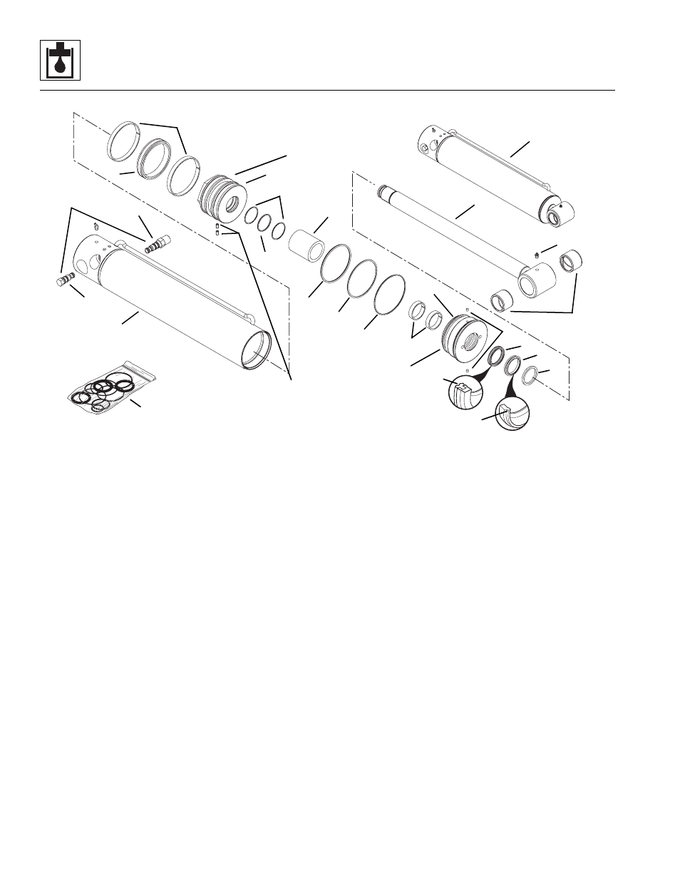
Figure 8-67 Attachment Tilt Cylinder Components
4. Install both precision wearbands (Fig. 8-67, 19) and
the capped T-seal (20) onto the piston (8).
Note: The T-seal actually consists of four components: a
wide, flexible inner band, the flexible T-seal band itself,
and two supportive split caps that mount on either side of
the “T” itself.
5. Install the head gland (Fig. 8 -67, 7) and rod spacer
(10) onto the rod (4).
IMPORTANT: Protect the finish on the rod at all times.
Damage to the surface of the rod can cause seal failure.
6. Install new setscrews (Fig. 8-67, 9) into the piston (8).
7. Fasten the rod end in a soft-jawed vise and put a
padded support below and near the threaded end of
the rod to help prevent damage to the rod. Apply
Loctite #243 and install the piston (Fig. 8-67, 8) onto
the rod (4). Torque the piston to 200-300 lb/ft
(271-407 Nm).
IMPORTANT: Avoid using excess force when clamping
the cylinder in a vise. Apply only enough force to hold the
cylinder securely. Excessive force can damage the cylinder.
8. Place the attachment tilt cylinder tube (Fig. 8-67, 2)
in a soft-jawed vise or other acceptable holding
equipment if possible.
IMPORTANT: When sliding the rod and piston assembly
in the tube, prevent the threaded end of the tube from
damaging the piston (Fig. 8-67, 8). Keep the rod
centered within the tube to help prevent binding.
9. Carefully insert the rod (Fig. 8-67, 4) with all
attachments straight into the tube (2).
10. Using a pin spanner wrench, thread the head gland
(Fig. 8-67, 7) almost completely into the tube (2),
leaving just enough room to install new locking
inserts (14) into the holes in the head gland.
11. Install new locking inserts (Fig. 8-67, 14). Thread
the head gland (7) tightly into the tube and torque to
300-400 lb/ft (407-542 Nm).
12. Using new oiled o-rings, thread the 4000 psi (276 bar)
counterbalance valve (Fig. 8-67, 5) and the pilot-
operated check valve (6) into the attachment tilt
cylinder. Torque to 30-35 lb/ft (41-47 Nm).
13. If necessary, install a grease fitting (Fig. 8 -67, 3) into
the tapped hole in the end of the rod (4). Lubricate
the bearings in the rod end through the grease fitting
with multi-purpose grease before the vehicle is
operated.
MA7100
6
1
2
9
8
16
19
10
15
11
12
13
14
7
18
4
5
21
17
Torque to
300-400 lb/ft
(407-542 Nm)
Apply Loctite #243 to
threads and torque to
200-300 lb/ft
(271-407 Nm)
Torque to
30-35 lb/ft
(41-47 Nm)
3
20
26
24
23
Apply Loctite #243 to
threads and torque to
155-175 lb/in
(18-20 Nm)
25
22