Chip thickness ( h – Sandvik Coromant Heat resistant super alloys User Manual
Page 96
94
100
90
80
70
60
50
40
30
20
10
0
35
25
22
11
100
90
80
70
60
50
40
30
20
10
0
22
16
11
min
min
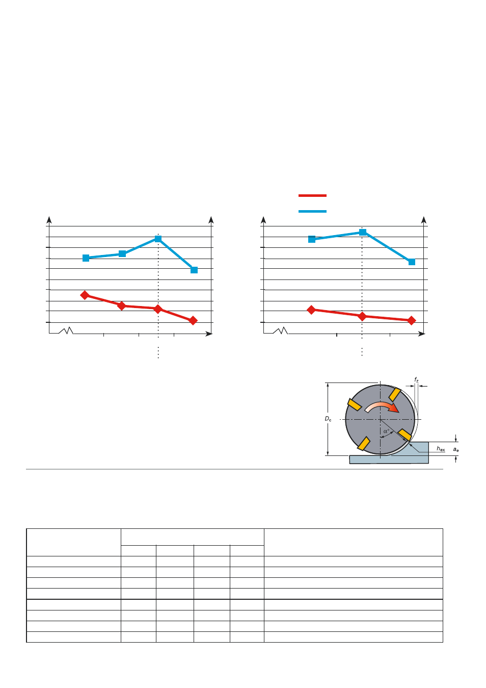
Chip thickness (h
ex
)
The low radial engagement reduces the
chip thickness compared to the feed per
tooth. Using the optimised chip thickness is
pivotal in optimisation of finishing, slicing or
trochoidal milling.
It can be seen in the diagram that a reduc-
tion of chip thickness reduces the material
removed due to rubbing rather than cutting.
Equally the tool life drops by as much as
50% when the chip thickness is increased
from 0.04 to 0.052 mm (25%). The best
results are achieved at 0.04 mm thickness.
0.02
0.03
0.04
0.052
Chip thickness,
mm
Tool life vs chip thickness – a
e
0.5 mm (4% of D
c
)
R216.24-12050-GAK26P 1620
v
c
75 m/min, a
p
10 mm,
Material: Inconel 718
70
74
87
59
0.028
0.04
0.055
Chip thickness,
mm
Tool life vs chip thickness – a
e
1.0 mm (8% of D
c
)
R216.24-12050-GAK26P 1620
v
c
75 m/min, a
p
10 mm
Material: Inconel 718
Tool life
Total metal removal
87
94
66
The chip thickness is a factor affected by the feed per
tooth and the angle of approach (radial engagement and
diameter of cutter).
Each cutting edge design has an optimum chip thickness for a particular operation/mate-
rial (0.04 mm for CoroMill Plura in Inconel). The feed rate selected should be that which
gives the optimum feed rate for the relative radial immersion (a
e
).
8
10
12
16
20.0%
1.6
2
2.4
3.2
53°
1.3
0.05
17.5%
1.4
1.75
2.1
2.8
49°
1.3
0.05
15.0%
1.2
1.5
1.8
2.4
46°
1.4
0.06
12.5%
1
1.25
1.5
2
41°
1.5
0.06
10.0%
0.8
1
1.2
1.6
37°
1.7
0.07
7.5%
0.6
0.75
0.9
1.2
32°
1.9
0.08
5.0%
0.4
0.5
0.6
0.8
26°
2.3
0.09
2.5%
0.2
0.25
0.3
0.4
18°
3.2
0.13
Depth of cut to
diameter ratio a
e
/D
c
Depth of cut for cutter diameter, mm
Entering
angle
α
Feed
modification
Feed f
z
for
0.04 h
ex
f
z
0.1
mm/tooth
f
z
0.08
mm/tooth
100
90
80
70
60
50
40
30
20
10
0
cm
3
100
90
80
70
60
50
40
30
20
10
0
cm
3