Circular ramping from solid, Cutter and hole diameter, Programmed feed rates – Sandvik Coromant Heat resistant super alloys User Manual
Page 109: Feed rate, Pitch, When using radius compensation • v, When using the tool centre feed, The axial pitch ( a
107
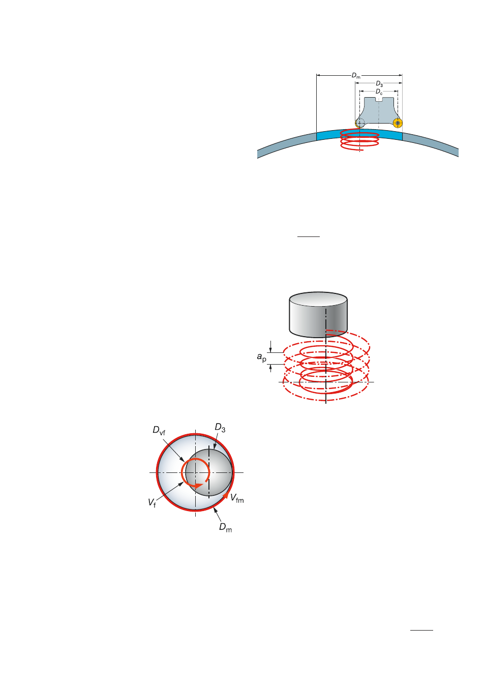
Cutter and hole diameter
The ramping process requires a cutter
which is capable of axial cutting. The dia-
meter selection is very important when
using cutters which are not centre cutting.
The diameter of the cutter, minus the insert
radius, should not exceed half the hole dia-
meter. This is to ensure that there is no
‘pip’ remaining.
D
vf
= D
m
– D
3
Programmed feed rates
•
v
fm
– when using radius compensation
•
v
f
– when using the tool centre feed
Circular ramping from solid
Example
D
m
= 58
D
3
= 35
v
c
= 25
f
z
= 0.2
D
vf
= 18
a
p
= 2
z
n
= 4
n
= 227
v
fm
= 182
v
f
= 76
Tool centre feed diameter – D
vf
Min D
m
= (D
3
– 0.5iC) x 2
D
m
2
Max D
3
= + 0.5iC
Feed rate
The feed rate must be reduced in internal
applications due to the periphery of the tool
moving faster than the centre line of the
tool.
Programming of the feed rate (mm/min)
on most milling machines/CAM systems
is based on the centre line of the spindle
requiring a manual recalculation.
Pitch
The axial pitch (a
p
) per revolution is deter-
mined by the max depth of cut limitation
for the cutter concept (0.15 x iC for round
inserts).
v
fm
= n x f
z
x z
n
Milling of holes is a flexible process able to
produce a range of hole sizes with each cut-
ter. It produces low axial cutting forces and
copes well with interrupted entrances and
exits which are a problem when machining
into curved surfaces such as casings.
D
vf
D
m
v
f
=
x v
fm