Geometries and chip breaking, Recommendation for tool geometry, 31 -sgf – Sandvik Coromant Heat resistant super alloys User Manual
Page 33: Smr -sf -sm, First choice
31
-SGF
CoroCut®
Q-Cut
SF
SGF
MF
*CGT-UM
SM
MM
MR
SM
QM
QM
GF
RO
RO
TF
TF
4G
4P
4P
5E
SM
1)
1)
SMR
SMR
SM
Xcel
a
p
f
n
-SMR
-SF
-SM
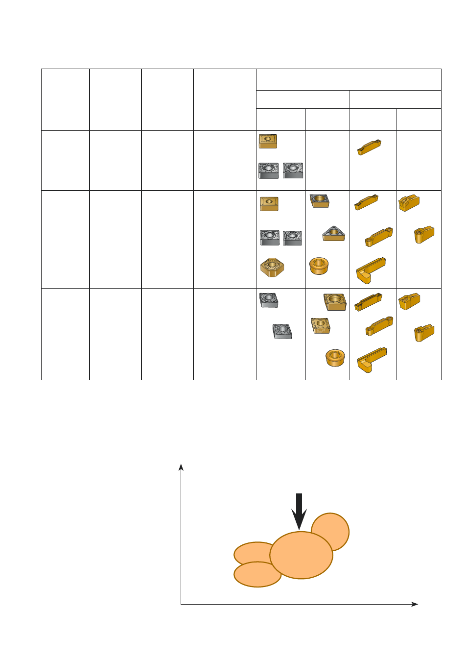
Geometries and chip breaking
Recommendation for tool geometry:
Application
area
Feed range,
mm
Edge
rounding
Geometry
requirements
Geometry recommendation
General turning
Grooving
Double
sided
Positive
Direct pressed
ground
Direct pressed
positive rake
angle
Direct pressed
– primary land
Medium
1) CoroCut angled inserts, see page 37.
Note: the ground inserts -SGF and *CGT-UM should be used for thin walled components to minimize the cutting
forces and hence risk of distortion.
ISM
0.15 to 0.25
LSM
0.1 to 0.2
Small
FSM
0.20 to 0.4
First choice
High feed rates,
interuptions
Lowest tool
pressure
Chip
breaking
ISO S geometries
First choice recom-
mendations for general
turning with double
sided inserts.
Medium to
small