Sandvik Coromant Heat resistant super alloys User Manual
Page 69
67
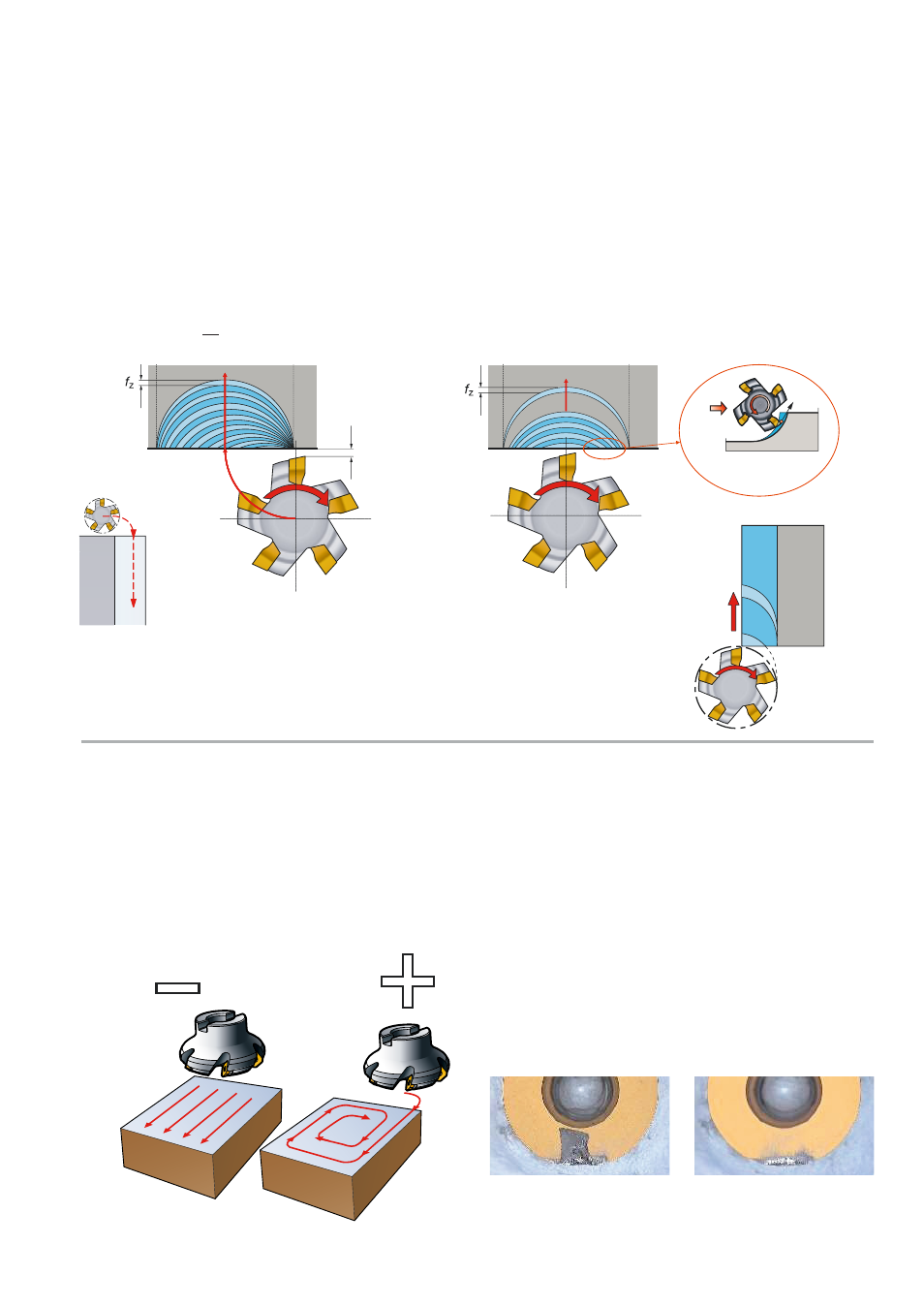
+
–
When profile milling the positioning of the
cutter can be pre-defined, however for face
milling where the position of the cutter is
more flexible it can be prone to misappli-
cation.
1) a
e
should not be greater than 75% of the
cutter diameter, and not less than 30% –
at least 2 teeth in contact (if z
n
> 2).
2) The cutter should be off-centre giving as
close to zero chip thickness as possible
on exit from cut.
3) Entry into the workpiece should be pro-
grammed carefully until the cutter is in
full cut by one of the following methods:
Reduced feed
on entry
Thick chip on exit
of cut until cutter is
fully engaged
Roll on entry
Prog. rad. =
(
D
e
)
+ 2
2
Also when milling large workpiece surface
areas, select tool path to keep the milling
cutter in full contact rather than perform
several parallel passes. When changing
direction, include a radial tool path to keep
cutter moving, avoiding dwell and chatter
tendencies.
Below, worn inserts with the same cutting
data and tool life in Waspalloy demonstrate
the impact of keeping the cutter in contact
with the workpiece.
Many entries/exits.
Constant contact.
2 mm