Chip thickness, Surface finish, Example – Sandvik Coromant Heat resistant super alloys User Manual
Page 21
19
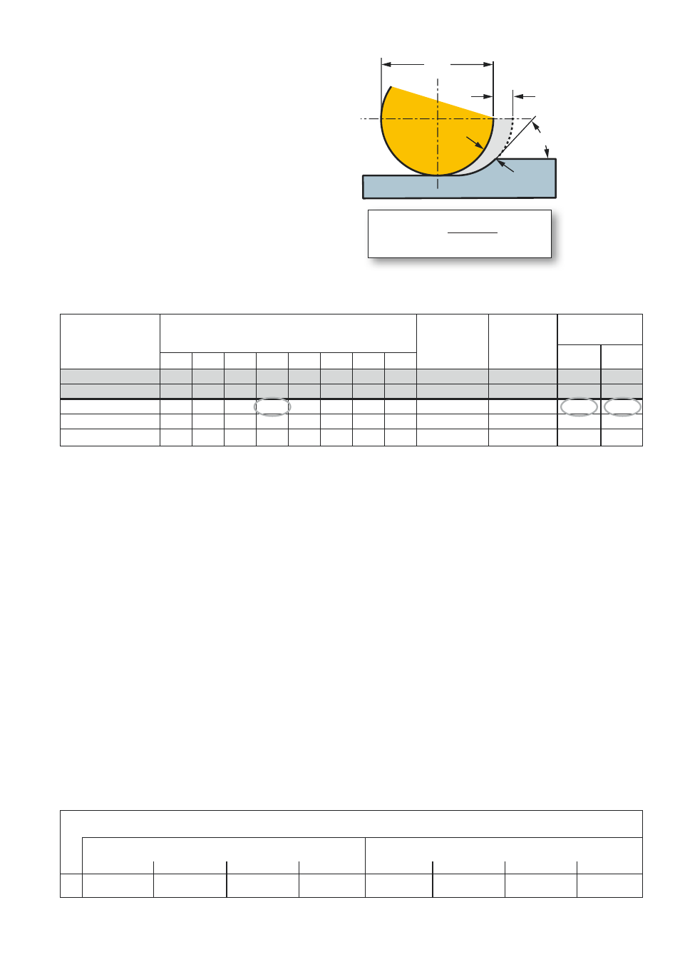
f
n
h
ex
k
r
f
n
iC
Chip thickness
The chip thickness varies with round
inserts, and depends upon the entering
angle. With low a
p
/iC ratios, the feed can
be increased in order to raise the chip
thickness to a desired level.
Recommended chip thicknesses h
ex
for
HRSA are:
Carbide
0.1 to 0.35 mm
Ceramic
0.08 to 0.15 mm
Depth of cut to
diameter ratio
a
p
/iC
Depth of cut for insert diameter, in mm
Entering
angle
k
r
Feed modi-
fication
value
Feed min/max
mm/r
h
ex
0.1
mm
h
ex
0.35
mm
6 mm diameter CoroCut RO insert.
Depth of cut 0.9 mm gives a maximum
entering angle
k
r
= 46°.
To machine with:
Minimum 0.1 mm chip thickness the cor-
rect feed is 0.14 mm/r.
Maximum 0.35 mm chip thickness the
correct feed is 0.49 mm/r.
The surface finish generated has a direct
relationship to both the nose radius size
and the feed rate. To achieve a certain
surface finish, a small nose radius requires
a lower feed rate than a large nose radius
– which in practical terms means that small
nose radius inserts lead to lower productiv-
ity.
Therefore, for the highest productivity the
nose radius should be as large as possible
– the largest of all being round inserts.
Nose radius size mm
Insert diameter mm
Maximum feed f
n
mm/r to achieve surface finish R
max
8.0 – R
a
1.6 µm – N7
Example
Surface finish
f
n
=
h
ex
sin
k
r
3
4
5
6
8
10
12
16
0.25
0.75
1
1.25 1.5
2
2.5
3
4
60°
1.16
0.12
0.41
0.2
0.6 0.8
1
1.2 1.6
2
2.4 3.2
53°
1.25
0.13
0.44
0.15
0.45 0.6 0.75 0.9 1.2 1.5 1.8 2.4
46°
1.4
0.14
0.49
0.1
0.3 0.4 0.5 0.6 0.8
1
1.2 1.6
37°
1.66
0.17
0.58
0.05
0.15 0.2 0.25 0.3 0.4 0.5 0.6 0.8
26°
2.3
0.23
0.81
0.4
0.8
1.2
1.6
8
10
12
16
0.17
0.22
0.27
0.32
0.5
0.57
0.62
0.7