Insert shape selection, Entering angle – Sandvik Coromant Heat resistant super alloys User Manual
Page 15
13
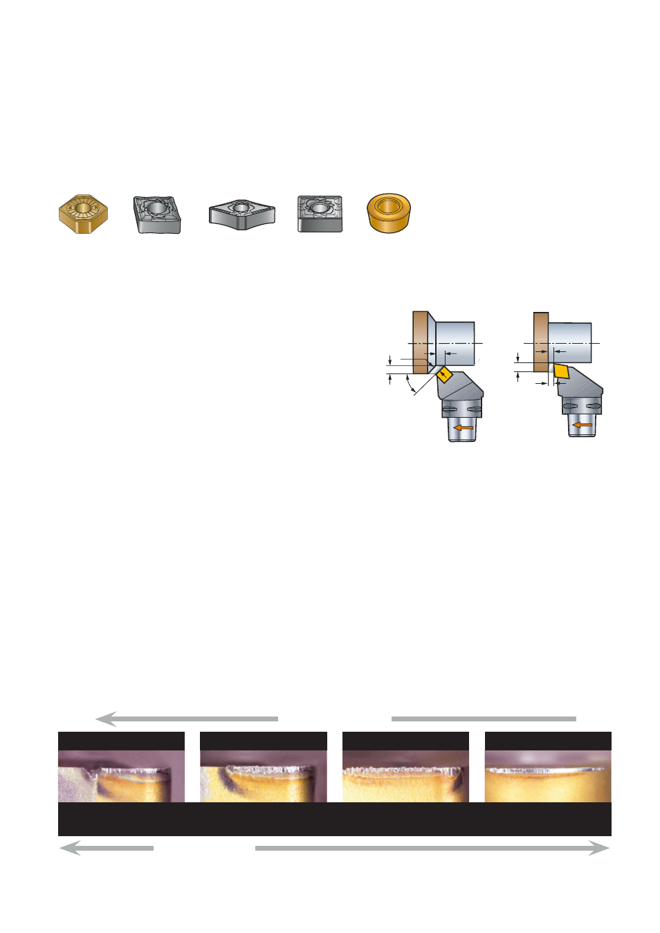
CNMG
DNMG
SNMG
CNMX
k
r
f
n
h
ex
≈ f
n
h
ex
h
ex
f
n
a
p
a
p
RCMT
h
ex
= f
n
x 0.71
Notch wear on the inserts is the major
problem when machining HRSA. The worst
notching occurs when the depth of cut is
greater than the nose radius, and the enter-
ing angle is 90°. (The depth of cut is the
influencing factor – with a depth of cut
smaller than the nose radius, the effective
entering angle is reduced even when the
angle on the insert itself is 90°).
By following some general rules the wear
can be controlled allowing more productive
grades to be used.
• Use as small entering angle as possible
(max 60°, min 25°)
– eg. SNMG, CNMX where
k
r
= 45°.
• Round inserts – use no greater entering
angle than 45° or 0.15 x diameter.
• Ramping – program a varying depth of cut
into the cutting operation. This spreads
the notching over the whole cutting edge,
giving longer tool life and more predict-
able wear. This method is used predomi-
nantly with ceramics, and mainly with
round inserts.
Insert shape selection
Entering angle –
k
r
With a standard C/D/SNMG style insert
for roughing, the entering angle is constant
regardless of depth of cut.
However, with round inserts the entering
angle varies from 0 to 90° depending upon
the ratio between depth of cut and diam-
eter.
Radial forces
High
Low
SNMG 45°
Round
Material: Inconel 718 (46 HRC) – a
p
2.0 mm, f
n
0.25 mm/rev, v
c
50 m/min – 5 min. time in cut
SNMG 75°
Notch
No notch
Effect of entering angle
Effect of entering angle on wear mechanism
h
ex
= chip thickness
CNMG 95°