Circular interpolation of existing holes, Circular interpolation of existing holes 108, Circular milling of existing hole – Sandvik Coromant Heat resistant super alloys User Manual
Page 110: The radial engagement ( a, Allowing for stability use d, 4 x d, And reduce feed by 50% of normal
108
5%
10%
15%
20%
25%
20%
40%
60%
80%
10
9
8
7
6
5
4
3
2
1
0
f
z
=
f
z
sinθ
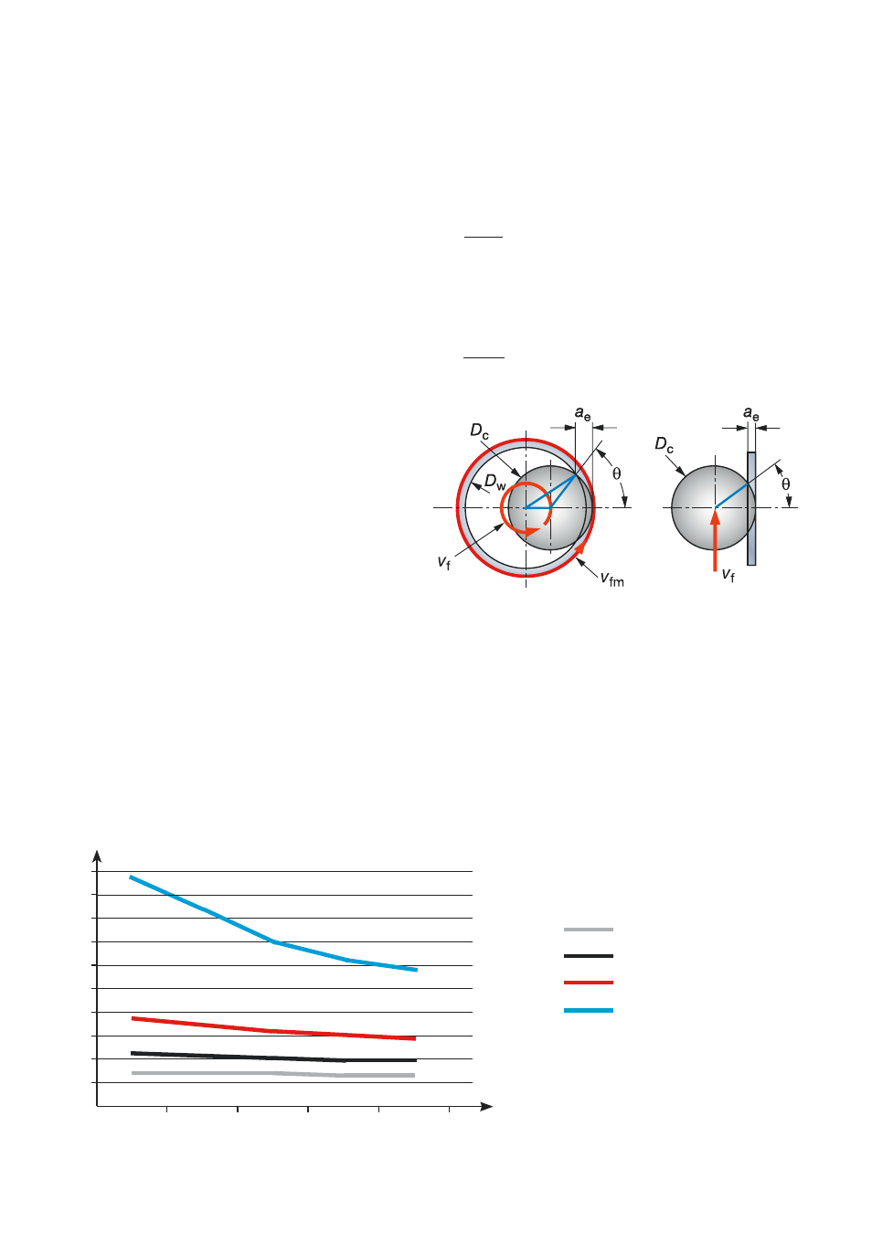
Hole diameters can be finish machined
using circular milling as an alternative to
boring depending on the surface finish
requirement. The feed rate (v
f
) must be
reduced compared to straight line milling
due to that in internal applications.
•
The periphery of the tool will be moving
faster than the centre line of the tool.
Programming of the feed rate (mm/min)
on most milling machines/CAM systems
is based on the centre line of the spin-
dle.
•
The radial engagement (a
e
) increases
compared to that of a straight cut
increasing the chip thickness, h
ex
.
•
The effect of both of these factors is
increased with the increase in cutter dia-
meter relative to the hole size.
•
The correct feed reduction compared to
straight cutting can be selected from the
diagram.
•
Allowing for stability use D
c
= 0.4 x D
m
and reduce feed by 50% of normal.
Tool centre feed reduction factor for given cutter dia.
hole dia. ratio (D
c
/D
m
) and constant chip thickness.
v
fm
= n x f
z
x z
n
D
vf
D
m
v
f
=
x v
fm
Percentage
a
e
/D
c
Feed reduction factor
Circular milling of existing hole