5-2 over-range indication/ bar indication, Warning, Caution – KYORITSU 6300 Instruction Manual User Manual
Page 79
6. 19
MODEL6300
Section 6 Instantaneous value measurement
MODEL6300
‣ ‧ • ⁈ ‥ • •⁈ • •⁈
‣ ⁂․⁉ ‣⁂‥ ⁉ ‥ ⁂‥ ⁉ ‥⁂… ⁉
‧ ″
‣• ″
․ •″
‧• ″
‣ • • ″ ․ • •″ ‧ • • ″ ‣ • • • ″
6-5-2 Over-range indication/ Bar indication
WARNING
Ɣ When the over-range indication appears on the maximum chosen range, this
means that the input exceeds the maximum allowable input for the instrument.
Never apply such an input to the instrument.
Ɣ When a measured value exceeds the maximum allowable input, the use of
VT/CT’s is recommended. Refer to “5-3 VT/ CT” and follow the instruction
manual.
CAUTION
Ɣ When over-range indication appears on the screen, calculations are still
performed. However their accuracy may not be guaranteed.
Ɣ Over-range indication
The Over-range indication appears when the parameters (Voltage V,
Current A, Active power P, Reactive power Q, Apparent power S) exceed
the following condition.
* Voltage V (V): >Voltage range selected x VT ratio x 120%
(e.g.: when voltage range is 300V and VT ratio is 1: 360.0V)
* Current A (A): > Current range x CT ratio x 120%
(e.g.: when current range selected is 200A and CT ratio is 2:
480.0A)
* Active power P (W)/ Reactive power Q (Var)/ Apparent power S (VA)
: > Power x VT ratio x CT ratio x 120%
(e.g.: when power is 60kW, VT ratio is 1 and CT ratio is 2: 144.0kW)
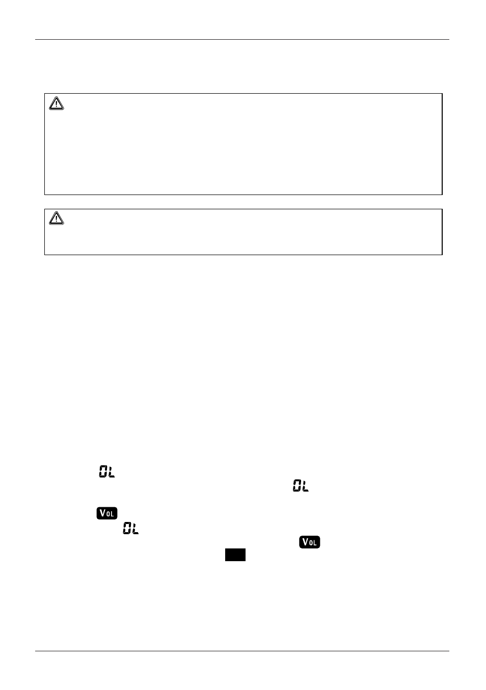
< indication >
When any of the above conditions are met, “ ” is displayed.
< mark>
When “ ” appears for over-range indication for any of V1, V2 and V3,
this is displayed on the LCD. In this case, the mark appears on all
measurement screens on the
W
position.
‣ ‧ • ⁈ ‥ •• ⁈ •• ⁈
‣ ⁂․ ⁉ ‣ ⁂‥ ⁉ ‥ ⁂‥ ⁉ ‥ ⁂… ⁉
‧ ″
‣ • ″
․ •″
‧ • ″
‣• • ″ ․ •• ″ ‧ •• ″ ‣• • • ″
‣ ‧ • ⁈ ‥ •• ⁈ •• ⁈
‣ ⁂․ ⁉ ‣ ⁂‥ ⁉ ‥ ⁂‥ ⁉ ‥ ⁂… ⁉
‧ ″
‣ • ″
․ •″
‧ • ″
‣• • ″ ․ •• ″ ‧ •• ″ ‣• • • ″