KYORITSU 6300 Instruction Manual User Manual
Page 18
MODEL6300
2. 4
MODEL6300
Section 2 Instrument layout
Section
2
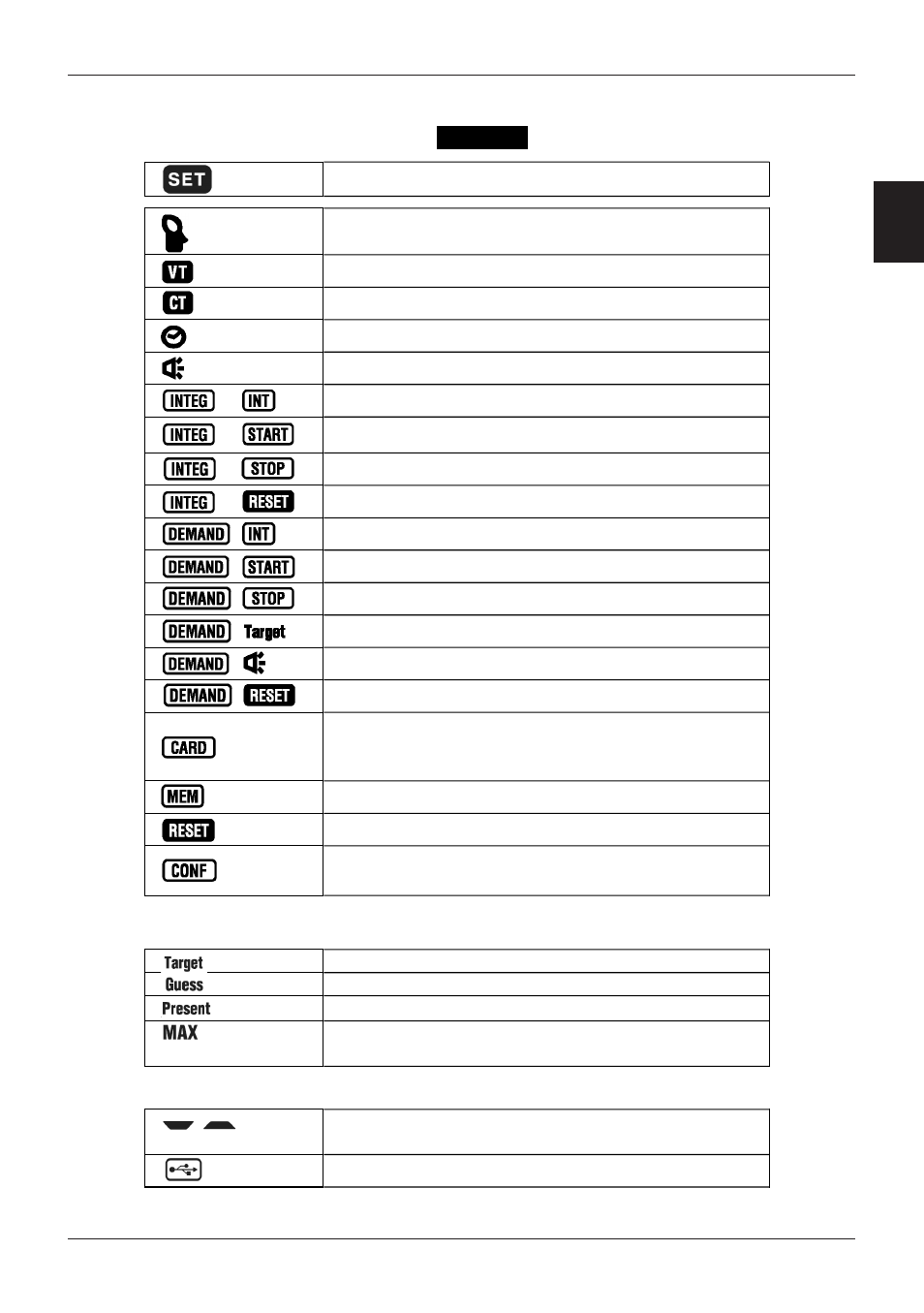
SET UP range depending on each setting.> Displayed on every setting screen. “Setting 04” Clamp sensor “Setting 05” VT ratio “Setting 06” CT ratio “Setting 07” Time “Setting 08” Buzzer “Setting 09” Integration interval “Setting 10” Integration start time & date “Setting 11” Integration stop time & date “Setting 12” Reset of Integration value “Setting 13” Demand interval “Setting 14” Demand start time & date “Setting 15” Demand stop time & date “Setting 16” Demand target value “Setting 17” Demand inspection cycle “Setting 18” Reset of Demand value “Setting 19” Use of CF card “Setting 22” Deleting the data in internal memory “Setting 23” System reset “Setting 24” Loading settings < Marks indicate measurement/ setting items on DEMAND range.> Demand target value Demand predicted value Present demand value Max demand value, and the time and date when it < Other marks> Indicates the selected wiring, voltage range and Displayed during data communication via USB.
“Setting 20” Formatting CF card
“Setting 21” Deleting the data in CF card
“Setting 25” Saving settings
was recorded.
current range