Connections for gen2 multi-lead probe, Overview, Connection procedure – Teledyne LeCroy Summit T3-16 PCIe Multi-lane Protocol Analyzer User Manual User Manual
Page 35: Components
Summit T3‐16 PCI Express Multi‐Lane Protocol Analyzer User Manual
23
Using Probes
Teledyne LeCroy
Connections for Gen2 Multi-lead Probe
Overview
Use a 1‐pod setup.
For x1 or x4, use the iPass Y‐cable to connect the probe data connectors on the Analyzer
to the pod(s).
On the other side of the pod, connect the flexible lead tips.
Connection Procedure
To connect Summit T3‐16 to the System Under Test (host platform or root complex under
test):
1. Connect the pods to the Analyzer using the iPass Y‐cable cables.
2. Connect the flexible lead tips to the pods using the SSMP cables.
3. Connect the lead tips to the system under test by soldering to the trace.
3.9.3
Example: Connecting the Summit T3-16 Analyzer to the Device Under Test
Using a Gen2 Multi-lead Probe for x8 and x16
Components
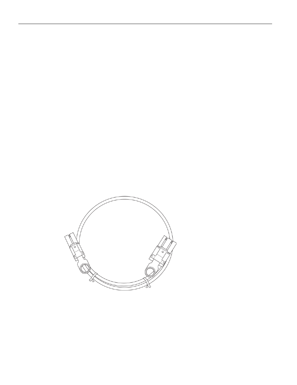
2 iPass Straight cables for x8 and 4 iPass Straight cables for x16
Figure 3.21: iPass Straight Cables
2 Multi‐lead Probe pods for x8
4 Multi‐lead Probe pods for x16
(See
“1 Multi‐lead Probe Pod for x1 and x4” on page 22
).
Up to 16 MidBus Probe SSMP Cables, and up to 8 Flexible Leads, per pod.
(See
1 Clock Cable (see
).