Teledyne LeCroy LabMaster 10Zi Getting Started Manual User Manual
Page 51
LabMaster 10 Zi Oscilloscopes
44
LM10Zi-GSM-E Rev A
you to make tip select and other probe settings from the oscilloscope
touchscreen.
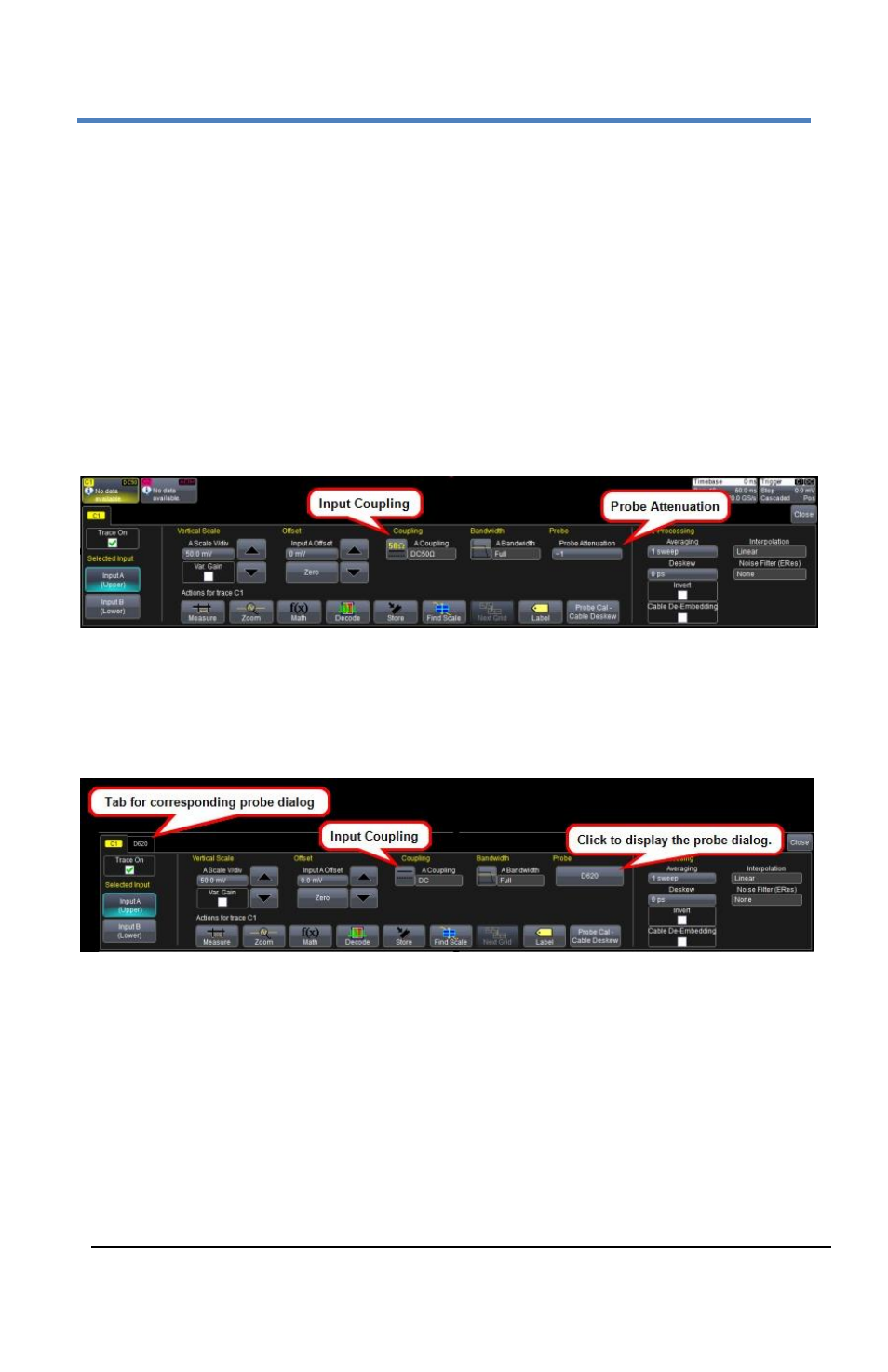
The following figure shows a typical channel setup dialog on a Teledyne
LeCroy oscilloscope containing both ProLink (Input A, Upper) and
ProBus (Input B, Lower) interfaces. The input selection is on the left-
hand side of the dialog box. In this case the A input, the ProLink
interface, is selected.
When the probe is not connected, there is only a C1 tab selection for
vertical channel setup and the user has the ability to select input
coupling and probe attenuation.
Channel dialog showing Input A's interface controls setup before connection.
After a probe is connected, it is recognized and an additional tab with
the probe model name is displayed to the right of the C1 tab. Click on
the tab or the probe field to display the probe dialog.
Channel dialog showing Input A's interface controls setup after connection.
This additional tab contains specific information on the connected
probe. Default values for the probes coupling and attenuation are
automatically downloaded from the probe, and these settings along
with other attributes are shown on the dialog.