Source code example gpib-3, Gpib program examples – Teledyne LeCroy X-STREAM OSCILLOSCOPES Remote Control User Manual
Page 269
GPIB Program Examples
WM-RCM-E Rev D
ISSUED: February 2005
263
N
N
O
O
T
T
E
E
:
:
¾
It is assumed that the National Instruments GPIB driver GPIB.COM is in its default state. This
means that the interface board can be referred to by its symbolic name ‘GPIB0’ and that devices
on the GPIB with addresses 1 to 16 can be called by the symbolic name ‘DEV1’ to ‘DEV16’.
¾
Lines 1–99 are a copy of the file DECL.BAS supplied by National Instruments. The first six lines
are required for the initialization of the GPIB handler. DECL.BAS requires access to the file
BIB.M during the GPIB initialization. BIB.M is one of the files supplied by National
Instruments, and must exist in the directory currently in use.
¾
The first two lines of DECL.BAS each contains a string “XXXXX” that must be replaced by the
number of bytes that determine the maximum workspace for BASICA (computed by subtracting
the size of BIB.M from the currently available space in BASICA). For example, if the size of
BIB.M is 1200 bytes and, when BASICA is loaded, it reports “60200 bytes free”, “XXXXX” would
be replaced by the value 59000 or less.
¾
The default timeout of 10 seconds is modified to 300 ms during the execution of this program.
However, the default value of the GPIB handler remains unchanged. Whenever a remote
command is entered by the user, the program sends it to the instrument with the function call
IBWRT. Afterwards, it always executes an IBRD call, regardless of whether or not a response is
expected. If a response is received it is immediately displayed. If there is no response, the
program waits until time-out and then asks for the next command.
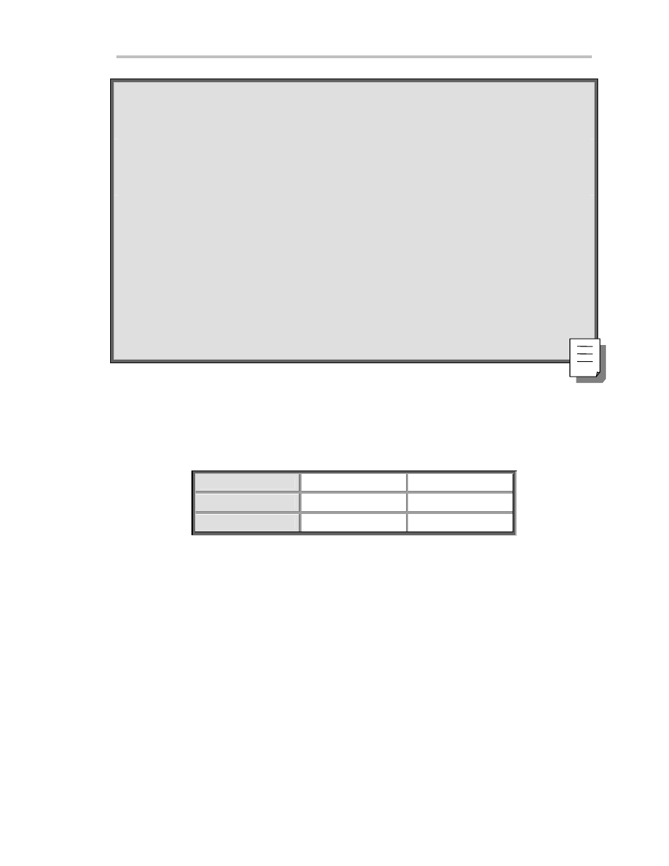
SOURCE CODE EXAMPLE GPIB - 3
USE GPIB Program for IBM PC (Low-Level Function Calls)
This example has the same function as Example 2, but is written with low-level function calls. The program
assumes that the controller (board) and oscilloscope (device) are at addresses 0 and 4, respectively, and the
decimal addresses are:
Listener Address
Talker Address
C
O N T R O L L E R
32(ASCII
64 (ASCII @)
D
E V I C E
32+4=36 (ASCII $)
64+4=68 (ASCII D)
‘
INCLUDE NATIONAL INSTRUMENTS GPIB ROUTINES
CLS
PRINT "Control of the 9300 (address 4) via GPIB and IBM PC" :
PRINT "Options : EX to exit LC local mode"
PRINT " ST store data RC recall data" : PRINT
UnListen$ = Chr$ ( 63) : UnTalk$ = Chr$ (95) ‘ General UnListen and
UnTalk