Ir input mode, Ir trig, Ger mode – Gilderfluke&Co Sd-50 Audio & Show Controllers User Manual
Page 29: Ir trigger mode
other Gilderfluke & Company devices. The only requirement is that they all be set to unique ad-
dresses.
Since RS-422 is probably the most widely used of industrial data networks, a myriad of other
pieces of equipment are available which will also work with the Net Serial mode. These allow you
to do tricks like controlling the Sd-50/8 or Sd-50/40 through a wireless modem using off-the-shelf
hardware.
A typical application is to use a touch screen operator interface to access and play shows.
These generally use a user definable graphical interface. You pretty much draw a button, and then
attach a string to it. When this on-screen button is pushed, this string is sent out to control the
downstream equipment.
IR Input Mode
The
switch on the bottom of the Sd-50/8 or Sd-50/40 can be in either
position, but RS-422 is preferred. This turns on a special serial port mode on the Sd-50/8 or Sd-50/
40 which allows it to be used with our InfraRed Transmitters and Receivers. The IR Remote mode
is typically used to trigger an animation or sound system mounted on a vehicle, turntable, or other
installation where wires can’t be used. The DMX-512/MIDI port is forced to 1200 baud and all serial
port commands are disabled on the DMX-512/MIDI port when this mode is ON. Any binary show
number received by the serial port for more than ten times will trigger the requested show. Typi-
cally the transmitters are placed along the path of the vehicle’s travel to trigger the appropriate
animation sequences at the appropriate times.
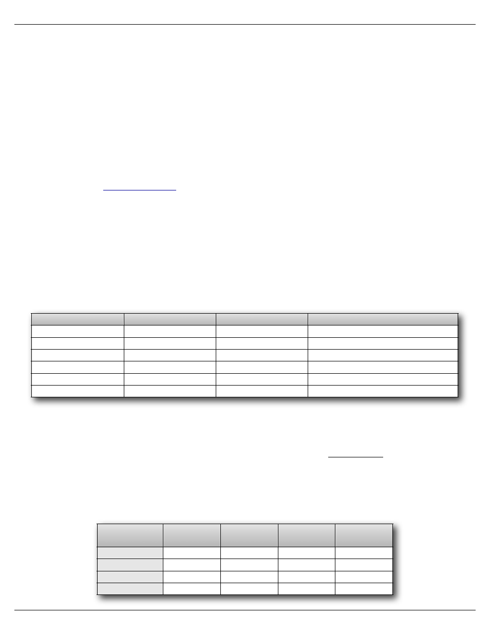
The connections to the IR Remote Receiver are as follows (view is facing end of cable with
latch up):
NAME
COLOR
SIGNAL FUNCTION
LEFT
Ground
WHITE
Ground
n/c
BLACK
no connection
n/c
RED
no connection
- TxD
GREEN
- DMX-512/MIDI Input
+ TxD
YELLOW
+ DMX-512/MIDI Input
RIGHT
Ground
BLUE
Ground
In addition to these connections, the IR Receiver requires a seven to twenty-four volt DC (Di-
rect Current) power supply connection. This is normally attached to the two pads marked “+” and
“-” on the receiver, or can be brought into the IR Receiver through the Black, Red or Blue Rj-12
wires. A jumper option allows you to bring this in through the blue wire on the RJ-11 connector.
When in this mode the ‘Early Starts’ for all shows should be set to ‘NOT Steppable’. If this is
not done, then the same show will be re-triggered over and over again until the vehicle moves out
of the IR beam from the transmitter.
The IR Transmitter has an eight position dipswitch which sets which show it selects. The lower
nibble of the address is set with the first four switches, and the upper nibble is set with the last four.
Valid show numbers are 01h through FFh:
Lower nibble
of Address
Switch #1
Switch #2
Switch #3
Switch #4
x0h
x1h
x2h
x3h
OFF
OFF
OFF
OFF
ON
OFF
OFF
OFF
OFF
ON
OFF
OFF
ON
ON
OFF
OFF
Gilderfluke & Co.• 205 South Flower Street • Burbank, California 91502 • 818/840-9484 • 800/776-5972 • fax 818/840-9485
Sd-50/xx Manual / October 29, 2012 2:29 PM / page 29 of 120