Gilderfluke&Co Sd-50 Audio & Show Controllers User Manual
Page 118
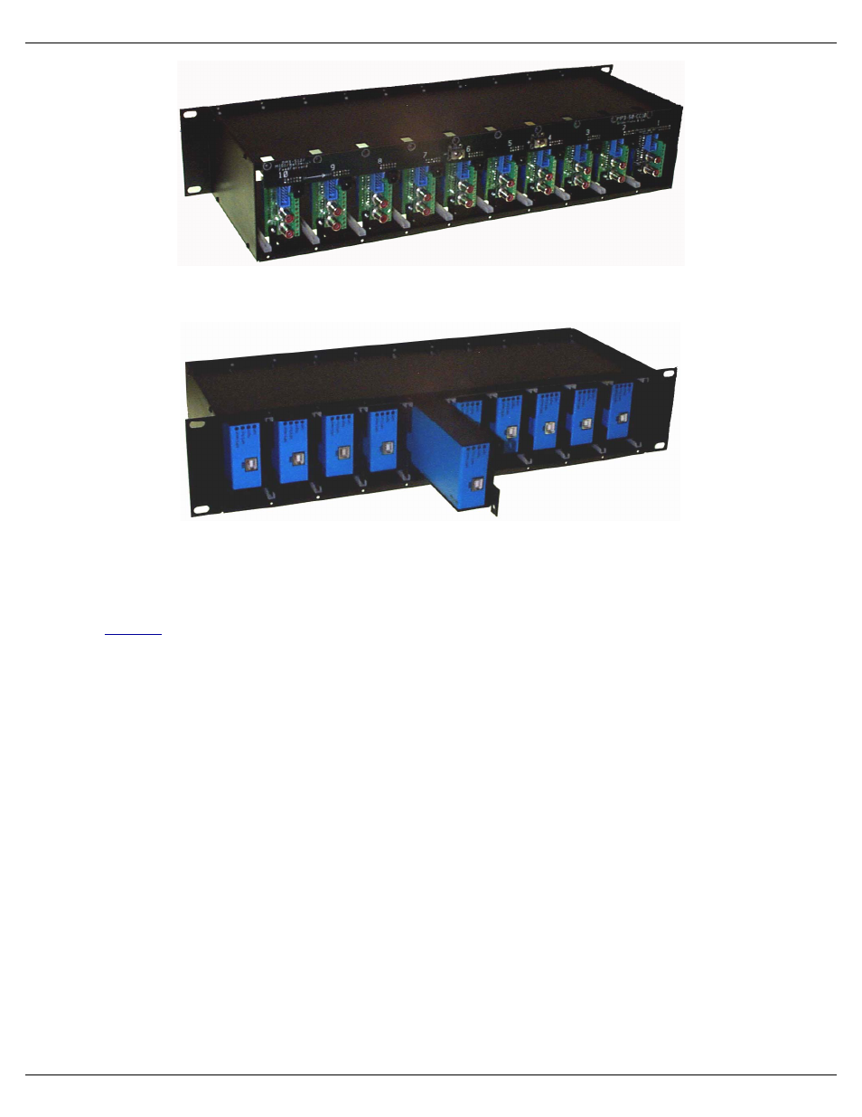
Now the Sd-50/xx can be plugged into the card cage. Nothing else needs to be removed or changed on the Sd-50/xx
before they inserted into the Sd-50/CC-10.
Power can be wired into any of the card cage positions, or through the heavy current screw terminals. The latter should
be used if you are using the amplifiers or Show Control outputs on Sd-50/8 or Sd-50/40 cards. This is because the total cur-
rent draw can exceed the capacity of the 2.1 mm power connector or smaller screw terminals located on the back of each
Sd-50.
The
serial port can be daisy chained from higher numbered slots towards lower number slots, but it is better
just to parallel them. Each Sd-50/xx will add a slight delay in the DMX-512 data, which may be unacceptable by the time
you reach the end of the cage.
If you are daisy chaining DMX-512, the Sd-50/xx that receives the initial DMX-512 connection can be set for isolated or
RS-422 operation. All the subsequent cards should be set for RS-422 operation. The signal is wired into the highest num-
bered populated slot and will be daisy chained through all the adjacent lower numbered slots. If a single slot is left unpopu-
lated, or populated with a Sd-50/0, will break the daisy chain. This can be used to divide the backplane into two or more
universes.
An Sd-50/xx can be converted back to stand-alone use by simply reversing the installation process. Remove the two
screws which hold the connector card into the Sd-50/CC-10, Plug it back into the Sd-50/xx, and secure it with the two
screws.
Gilderfluke & Co.• 205 South Flower Street • Burbank, California 91502 • 818/840-9484 • 800/776-5972 • fax 818/840-9485
Sd-50/xx Manual / October 29, 2012 2:29 PM / page 118 of 120