Extron Electronics DVS 510 Series User Guide User Manual
Page 16
DVS 510 Series • Installation
10
j
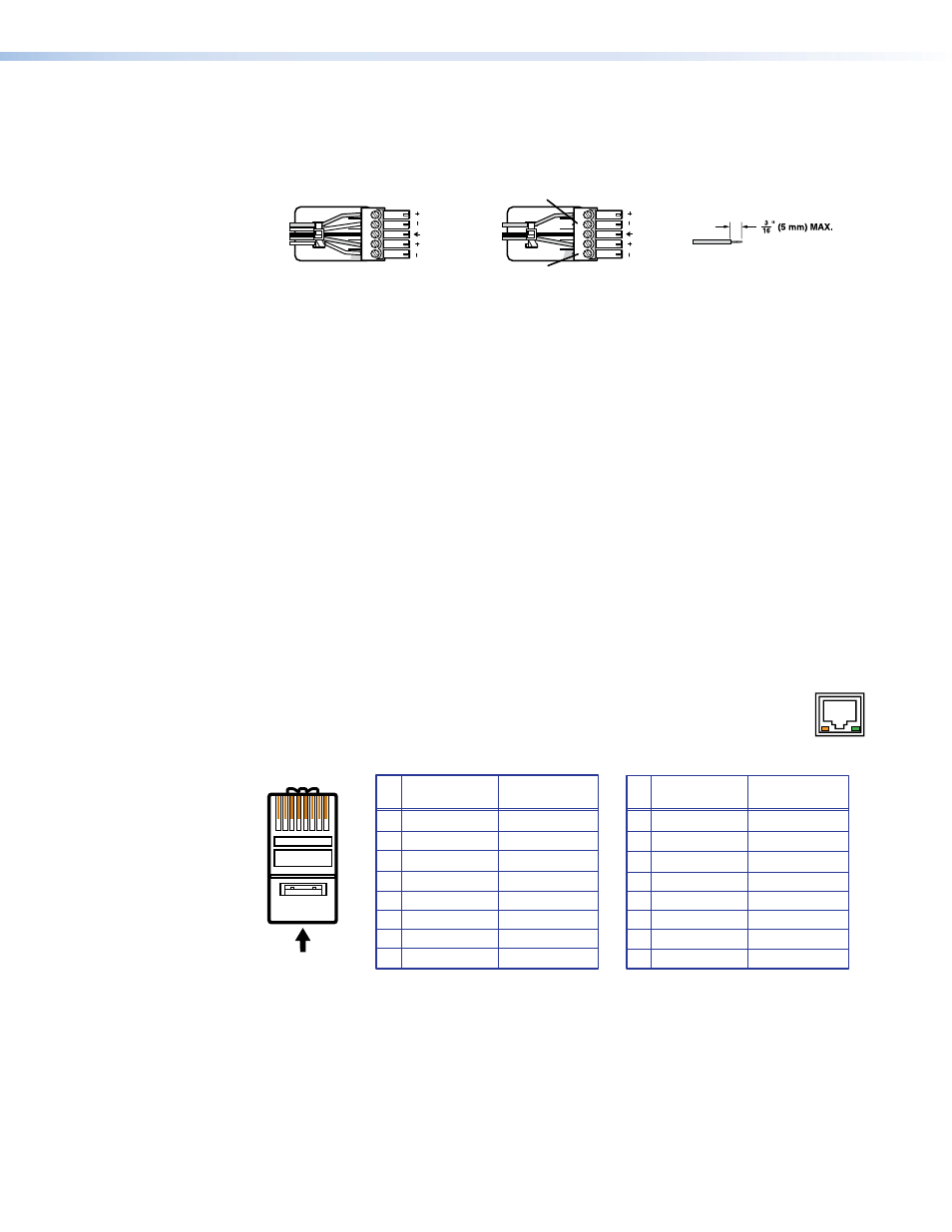
Variable audio output connector — Connect an audio device to this female 5-pole
3.5 mm captive screw connector for balanced or unbalanced variable audio output.
This output is affected by tone control, gain, attenuation, and audio delay. Wire the
connector as shown below.
Do not tin the wires!
Balanced Audio Output
Tip
Ring
Tip
Ring
Sleeves
Unbalanced Audio Output
Tip
No Ground Here
No Ground Here
Tip
Sleeves
LR
LR
Figure 5.
Audio Output Connector Wiring
k
Fixed audio output connector — Connect an audio device to this female 5-pole
3.5 mm captive screw connector for balanced or unbalanced fixed audio output. This
output is not affected by tone control; however, it is affected by gain, attenuation, and
audio delay. Wire the connector as shown in figure 5, above.
l
Reset LED — This green LED lights steadily while power is on. While the reset button is
being pressed and held, it blinks the number of times to indicate the reset mode.
m
Reset button — Using a small screwdriver, pointed stylus, or ballpoint pen, press this
recessed button for manual resets. The unit has four modes of reset (see “
on page 40 for additional information).
n
LAN connector — Plug an Ethernet cable into this RJ-45 jack to connect the unit to
a computer network. Ethernet control allows you to configure and control the scaler
from a remote location using SIS commands, the SPPCP software, or the embedded
web pages. When connected to an Ethernet LAN or WAN, the DVS can be accessed and
operated from a computer running a standard Internet browser.
Use a patch cable to connect the DVS to a switch, hub, or router; use a straight-through
cable to connect it directly to your computer.
This connector contains two LEDs (see the illustration at right):
•
Act LED — This amber LED blinks to indicate LAN signal activity.
•
Link LED — This green LED lights steadily to indicate a LAN connection.
A cable that is wired as T568A at one end
and T568B at the other (Tx and Rx pairs
reversed) is a "crossover" cable.
A cable that is wired the same at both ends
is called a "straight-through" cable, because
no pin or pair assignments are swapped.
RJ-45
Connector
Insert Twisted
Pair Wires
12345678
Pins:
Crossover Cable
Straight-through Cable
Pin
1
2
3
4
5
6
7
8
Wire color
White-green
Green
White-orange
Blue
White-blue
Orange
White-brown
Brown
Wire color
T568A
T568B
End 1
End 2
End 1
End 2
White-orange
Orange
White-green
Blue
White-blue
Green
White-brown
Brown
Pin
1
2
3
4
5
6
7
8
Wire color
Blue
White-blue
White-brown
Brown
Wire color
T568B
T568B
White-orange
White-orange
Orange
Orange
White-green
White-green
Blue
White-blue
Green
Green
White-brown
Brown
Figure 6.
Wiring the LAN Connector
ACT LINK
ETHERNET