Rainbow Electronics DS3131 User Manual
Page 71
DS3131
71 of 174
Register Name:
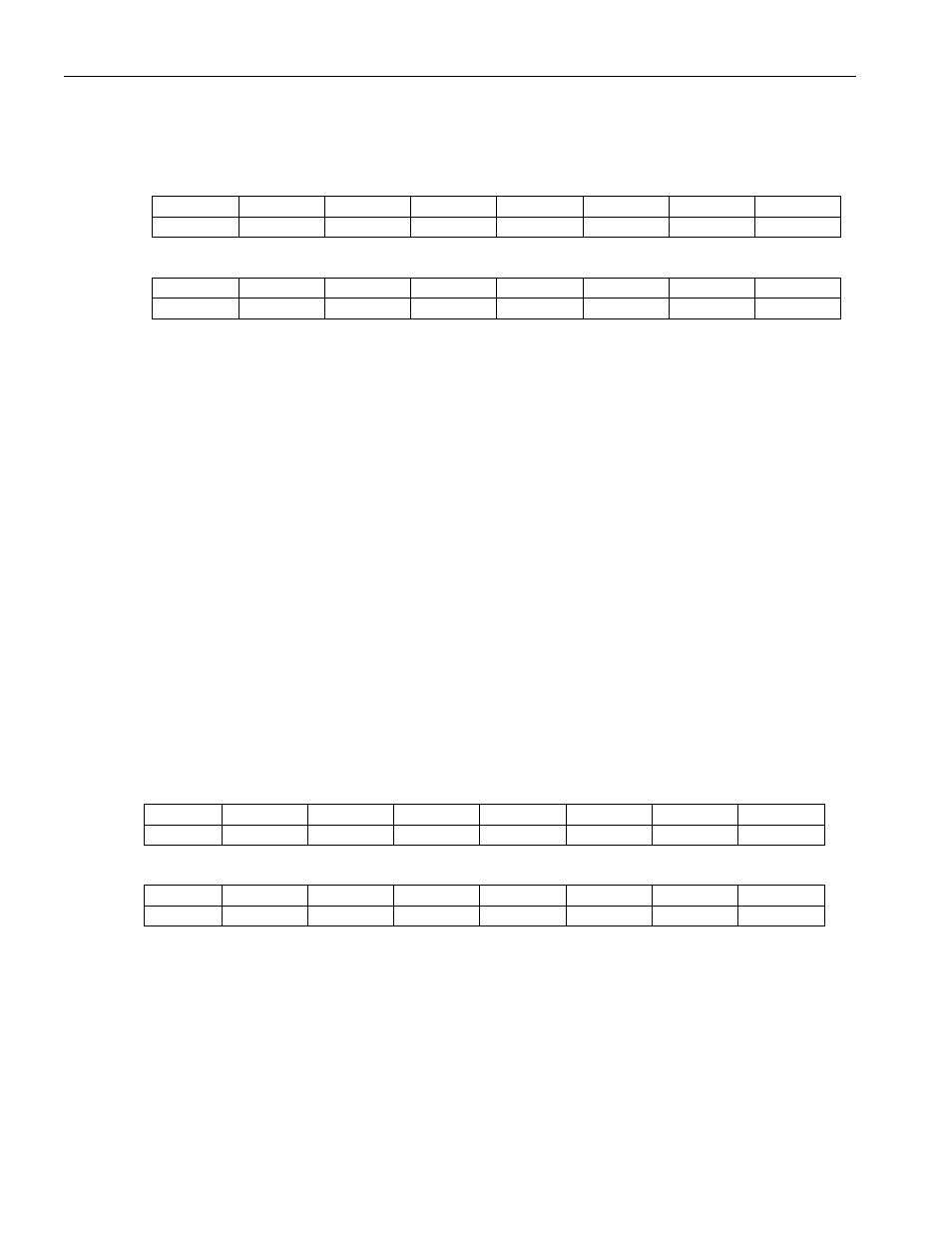
TFSBPIS
Register Description:
Transmit FIFO Starting Block Pointer Indirect Select
Register Address:
0980h
Bit
# 7 6 5 4 3 2 1 0
Name
reserved reserved HCID5 HCID4 HCID3 HCID2 HCID1 HCID0
Default 0 0 0 0 0 0 0 0
Bit
#
15 14 13 12 11 10 9 8
Name
IAB
IARW reserved reserved reserved reserved reserved reserved
Default 0 0 0 0 0 0 0 0
Note:
Bits that are underlined are read-only; all other bits are read-write.
Bits 0 to 5/HDLC Channel ID (HCID0 to HCID5)
000000 (00h) = HDLC channel number 1
100111 (27h) = HDLC channel number 40
Bit 14/Indirect Access Read/Write (IARW). When the host wishes to read data from the current internal
transmit block pointer, this bit should be written to 1 by the host. This causes the device to begin obtaining the
data from the channel location indicated by the HCID bits. During the read access, the IAB bit is set to 1. Once the
data is ready to be read from the TFSBP register, the IAB bit is set to 0. When the host wishes to write data to the
internal transmit starting block pointer RAM, this bit should be written to 0 by the host. This causes the device to
take the data that is currently present in the TFSBP register and write it to the channel location indicated by the
HCID bits. When the device has completed the write, the IAB is set to 0.
Bit 15/Indirect Access Busy (IAB). When an indirect read or write access is in progress, this read-only bit is set
to 1. During a read operation, this bit is set to 1 until the data is ready to be read. It is set to 0 when the data is
ready to be read. During a write operation, this bit is set to 1 while the write is taking place. It is set to 0 once the
write operation has completed.
Register Name:
TFSBP
Register Description:
Transmit FIFO Starting Block Pointer
Register Address:
0984h
Bit
# 7 6 5 4 3 2 1 0
Name
TSBP7 TSBP6 TSBP5 TSBP4 TSBP3 TSBP2 TSBP1 TSBP0
Default
Bit
# 15 14 13 12 11 10 9 8
Name
reserved reserved reserved reserved reserved reserved reserved TSBP8
Default
Note:
Bits that are underlined are read-only; all other bits are read-write.
Bits 0 to 8/Starting Block Pointer (TSBP0 to TSBP8). These bits determine which of the 512 blocks within the
transmit FIFO the host wants the device to configure as the starting block for a particular HDLC channel. Any of
the blocks within a chain of blocks for an HDLC channel can be configured as the starting block. When these nine
bits are read, they report the current block pointer being used to read data from the transmit FIFO by the HDLC
controllers.
000000000 (000h) = use block 0 as the starting block
111111111 (1ffh) = use block 511 as the starting block