Rainbow Electronics DS3131 User Manual
Page 70
DS3131
70 of 174
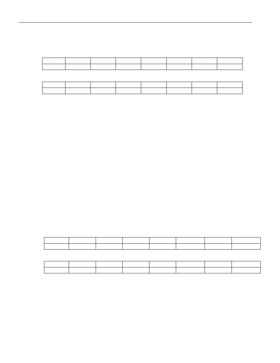
Register Name:
RFHWMIS
Register Description:
Receive FIFO High-Watermark Indirect Select
Register Address:
0920h
Bit
# 7 6 5 4 3 2 1 0
Name reserved
reserved HCID5 HCID4 HCID3 HCID2 HCID1 HCID0
Default
0 0 0 0 0 0 0 0
Bit
# 15 14 13 12 11 10 9 8
Name
IAB
IARW reserved reserved reserved reserved reserved reserved
Default
0 0 0 0 0 0 0
Note:
Bits that are underlined are read-only; all other bits are read-write.
Bits 0 to 5/HDLC Channel ID (HCID0 to HCID5)
000000 (00h) = HDLC channel number 1
100111 (27h) = HDLC channel number 40
Bit 14/Indirect Access Read/Write (IARW). When the host wishes to read data from the internal receive high-
watermark RAM, this bit should be written to 1 by the host. This causes the device to begin obtaining the data
from the channel location indicated by the HCID bits. During the read access, the IAB bit is set to 1. Once the data
is ready to be read from the RFHWM register, the IAB bit is set to 0. When the host wishes to write data to the
internal receive high-watermark RAM, this bit should be written to 0 by the host. This causes the device to take
the data that is currently present in the RFHWM register and write it to the channel location indicated by the HCID
bits. When the device has completed the write, the IAB is set to 0.
Bit 15/Indirect Access Busy (IAB). When an indirect read or write access is in progress, this read-only bit is set
to 1. During a read operation, this bit is set to 1 until the data is ready to be read. It is set to 0 when the data is
ready to be read. During a write operation, this bit is set to 1 while the write is taking place. It is set to 0 once the
write operation has completed.
Register Name:
RFHWM
Register Description:
Receive FIFO High Watermark
Register Address:
0924h
Bit
# 7 6 5 4 3 2 1 0
Name
RHWM7 RHWM6 RHWM5 RHWM4 RHWM3 RHWM2 RHWM1 RHWM0
Default
Bit #
15
14
13
12
11
10
9
8
Name
reserved reserved reserved reserved reserved reserved reserved RHWM8
Default
Note:
Bits that are underlined are read-only; all other bits are read-write.
Bits 0 to 8/High Watermark (RHWM0 to RHWM8). These bits indicate the setting of the receive high-
watermark. The high-watermark setting is the number of successive blocks that the HDLC controller writes to the
FIFO before the DMA sends the data to the PCI bus. The high-watermark setting must be between (inclusive) one
block and one less than the number of blocks in the link-list chain for the particular channel involved. For
example, if four blocks are linked together, the high watermark can be set to either 1, 2, or 3.
000000000 (000h) = invalid setting
000000001 (001h) = high watermark is 1 block
000000010 (002h) = high watermark is 2 blocks
111111111 (1ffh) = high watermark is 511 blocks