Rainbow Electronics DS3131 User Manual
Page 42
DS3131
42 of 174
Register Name:
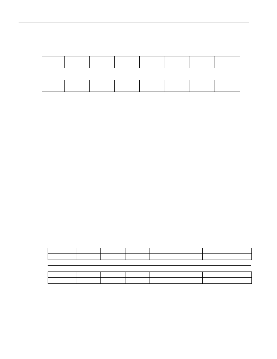
ISM
Register Description:
Interrupt Mask Register for SM
Register Address:
0024h
Bit
# 7 6 5 4 3 2 1 0
Name
reserved reserved reserved PPERR PSERR SBERT reserved reserved
Default
0 0 0 0 0 0 0 0
Bit
# 15 14 13 12 11 10 9 8
Name
LBINT LBE reserved reserved reserved reserved reserved reserved
Default
0 0 0 0 0 0 0 0
Note:
Bits that are underlined are read-only; all other bits are read-write.
Bit 2/Status Bit for Change of State in BERT (SBERT)
0 = interrupt masked
1 = interrupt unmasked
Bit 3/Status Bit for PCI System Error (PSERR)
0 = interrupt masked
1 = interrupt unmasked
Bit 4/Status Bit for PCI System Error (PPERR)
0 = interrupt masked
1 = interrupt unmasked
Bit 14/Status Bit for Local Bus Error (LBE)
0 = interrupt masked
1 = interrupt unmasked
Bit 15/Status Bit for Local Bus Interrupt (LBINT)
0 = interrupt masked
1 = interrupt unmasked
Register Name:
SDMA
Register Description:
Status Register for DMA
Register Address:
0028h
Bit
#
7 6 5 4 3 2 1 0
Name RLBRE RLBR ROVFL RLENC RABRT RCRCE reserved reserved
Default
0 0 0 0 0 0 0 0
Bit
#
15 14 13 12 11 10 9 8
Name TDQWE TDQW TPQR TUDFL RDQWE RDQW RSBRE RSBR
Default
0 0 0 0 0 0 0 0
Note:
Bits that are underlined are read-only; all other bits are read-write.
Bit 2/Status Bit for Receive HDLC CRC Error (RCRCE). This status bit is set to 1 if any of the receive HDLC
channels experiences a CRC checksum error. The RCRCE bit is cleared when read and is not set again until
another CRC checksum error has occurred. If enabled through the RCRCE bit in the interrupt mask for SDMA
(ISDMA), the setting of this bit causes a hardware interrupt at the PCI bus through the PINTA signal pin and also
at the LINT if the local bus is in configuration mode.