Bert, Bert r, Egister – Rainbow Electronics DS3131 User Manual
Page 51: Escription, Figure 6-3. bert register set, 3 bert, Figure 6-2. bert mux diagram
DS3131
51 of 174
6.3 BERT
The BERT block is capable of generating and detecting the following patterns:
The pseudorandom patterns 2E7, 2E11, 2E15, and QRSS
A repetitive pattern from 1 to 32 bits in length
Alternating (16-bit) words which flip every 1 to 256 words
The BERT receiver has a 32-bit bit counter and a 24-bit error counter. It can generate interrupts upon
detecting a bit error, a change in synchronization, or if an overflow occurs in the bit and error counters.
See Section
5
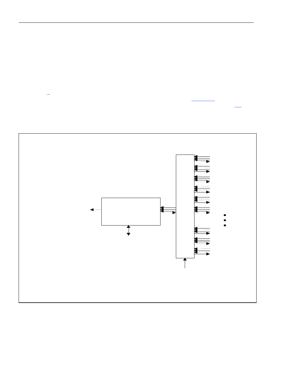
for details on status bits and interrupts from the BERT block. To activate the BERT block,
the host must configure the BERT mux through the master control register (
Figure 6-2
); the TBS select
bit in the TP[n]CR register must be set to 1 to have the BERT data appear at the TD pin (Section
6.2
).
Figure 6-2. BERT Mux Diagram
PORT 0
PORT 1
PORT 2
PORT 3
PORT 4
PORT 5
BERT
MUX
BERT SELECT BITS (6)
IN THE MASTER CONTROL
REGISTER
BERT BLOCK
SBERT STATUS BIT IN SM
INTERNAL CONTROL
AND CONFIGURATION BUS
PORT 37
PORT 38
PORT 39