Tap controller state machine description, Nstruction, Egister and – Rainbow Electronics DS3131 User Manual
Page 156: Nstructions, Figure 13-1. layer 1 port ac timing diagram, 2 tap controller state machine description, Figure 12-2. tap controller state machine
DS3131
156 of 174
12.2
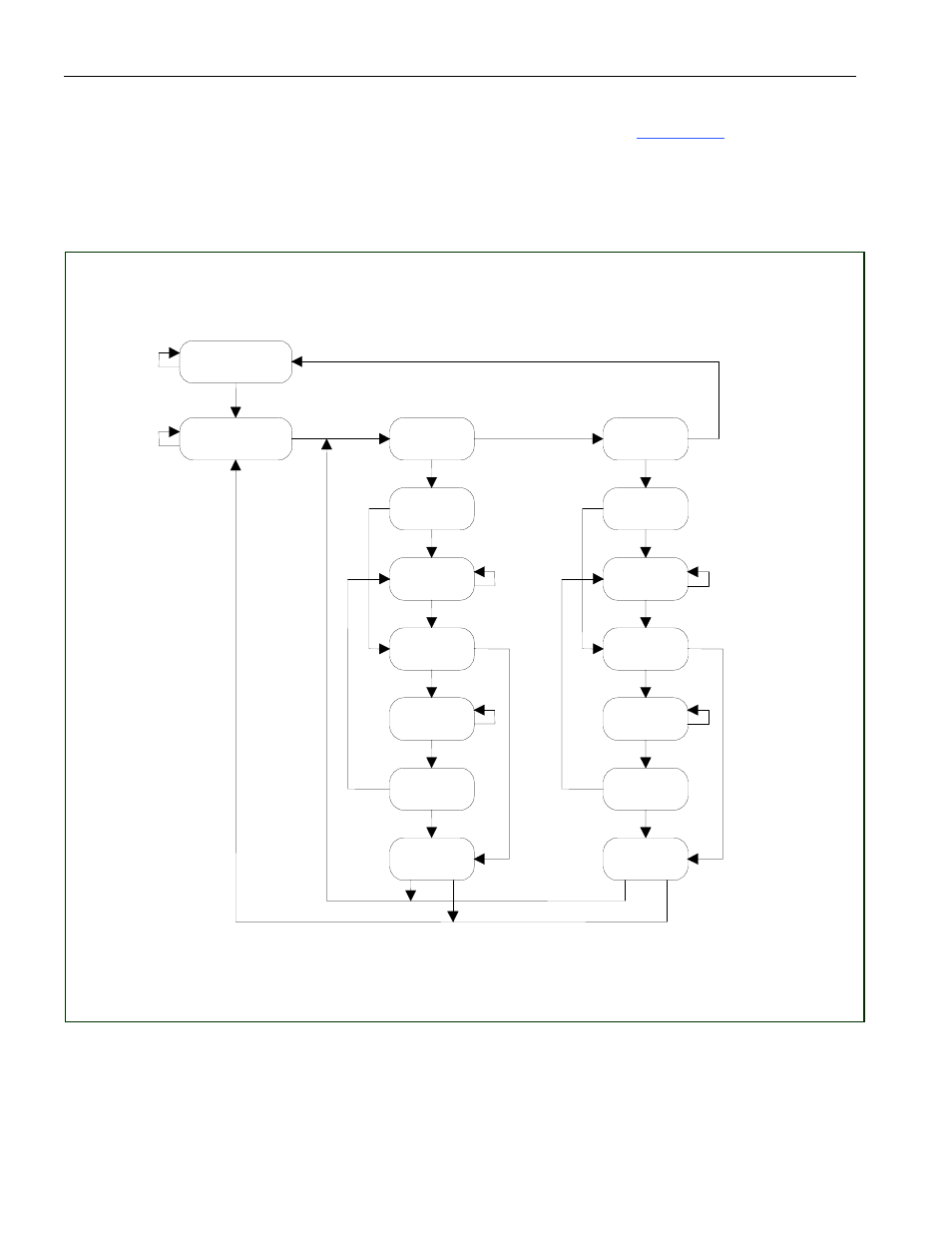
TAP Controller State Machine Description
This section details the operation of the TAP controller state machine. See
Figure 12-2
for details about
each of the states described below. The TAP controller is a finite state machine, which responds to the
logic level at JTMS on the rising edge of JTCLK.
Figure 12-2. TAP Controller State Machine
Test-Logic-Reset
Run-Test/Idle
Select
DR-Scan
1
0
Capture-DR
1
0
Shift-DR
0
1
Exit1-DR
1
0
Pause-DR
1
Exit2-DR
1
Update-DR
0
0
1
Select
IR-Scan
1
0
Capture-IR
0
Shift-IR
0
1
Exit1-IR
1
0
Pause-IR
0
Exit2-IR
1
Update-IR
0
0
1
0
0
1
0
1
0
1
See also other documents in the category Rainbow Electronics Communication:
- MAX12005 (14 pages)
- MAX7058 (14 pages)
- MAX9995 (13 pages)
- MAX7034 (13 pages)
- MAX7033 (16 pages)
- MAX9476 (8 pages)
- MAX9486 (8 pages)
- MAX14821 (29 pages)
- MAX9489 (11 pages)
- MAX9491 (11 pages)
- DS2130Q (22 pages)
- DS21458 (270 pages)
- DS26502 (125 pages)
- DS2153Q (48 pages)
- DS26503 (123 pages)
- DS2186 (11 pages)
- DS1842A (6 pages)
- DS3134 (203 pages)
- DS1876 (69 pages)
- DS1874 (88 pages)
- DS31256 (181 pages)
- DS2141A (35 pages)
- DS3184 (13 pages)
- DS2154 (69 pages)
- DS26504 (128 pages)
- DS3164 (12 pages)
- DS1852 (25 pages)
- DS2181A (32 pages)
- DS2151Q (46 pages)
- DS1843 (8 pages)
- DS2165Q (17 pages)
- DS3170 (233 pages)
- DS2180A (36 pages)
- DS2172 (20 pages)
- DS2152 (79 pages)
- DS1841 (16 pages)
- DS2182A (22 pages)
- DS2143Q (40 pages)
- DS2132A_Q (17 pages)
- DS1862 (42 pages)
- DS26519 (310 pages)
- DS2188 (11 pages)
- DS1875 (92 pages)
- DS33M33 (20 pages)