Dma configuration ram, Pci bus, Figure 10-1. pci configuration memory map – Rainbow Electronics DS3131 User Manual
Page 116: 5 dma configuration ram, Figure 9-21. transmit dma configuration ram
DS3131
116 of 174
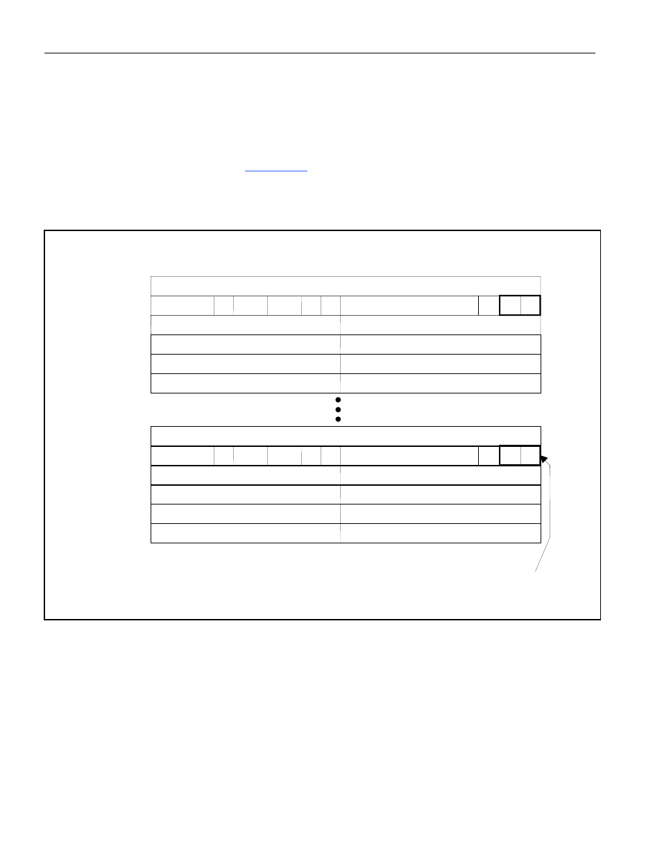
9.3.5 DMA Configuration RAM
The device contains an on-board set of 240 dwords (6 dwords per channel times 40 channels) that are
used by the host to configure the DMA and used by the DMA to store values locally when it is
processing a packet. Most of the fields within the DMA configuration RAM are for DMA use and the
host never writes to these fields. The host is only allowed to write (configure) to the lower word of
dword 1 for each HDLC channel. In
Figure 9-21
, the host-configurable fields are denoted with a thick
box.
Figure 9-21. Transmit DMA Configuration RAM
MSB
31
LSB
0
Transmit DMA Configuration RAM
Fields shown within the thick box
are written by the host; all other
fields are for DMA use and can
only be read by the host.
Next Descriptor Pointer (16)
Next Priority Pending Descriptor Pointer (16)
Byte Count (13)
Current Packet Data Buffer Address (32)
Start Descriptor Pointer (16)
CH
EN
Last Pending Descriptor Pointer (16)
Next Pending Descriptor Pointer (16)
Next Priority Descriptor Pointer (16)
Last Priority Pending Descriptor Pointer (16)
DQS
unused (16)
EOF CV
PEND
ST(2)
PRI
ST(2)
unused (9)
PPP
un-
used
dword 0
dword 1
dword 2
HDLC
CH 40
dword 3
dword 4
dword 5
dword 0
dword 1
dword 2
HDLC
CH 1
dword 3
dword 4
dword 5