D.36 msrn – Intel 386 User Manual
Page 604
D-39
SYSTEM REGISTER QUICK REFERENCE
D.36 MSR
n
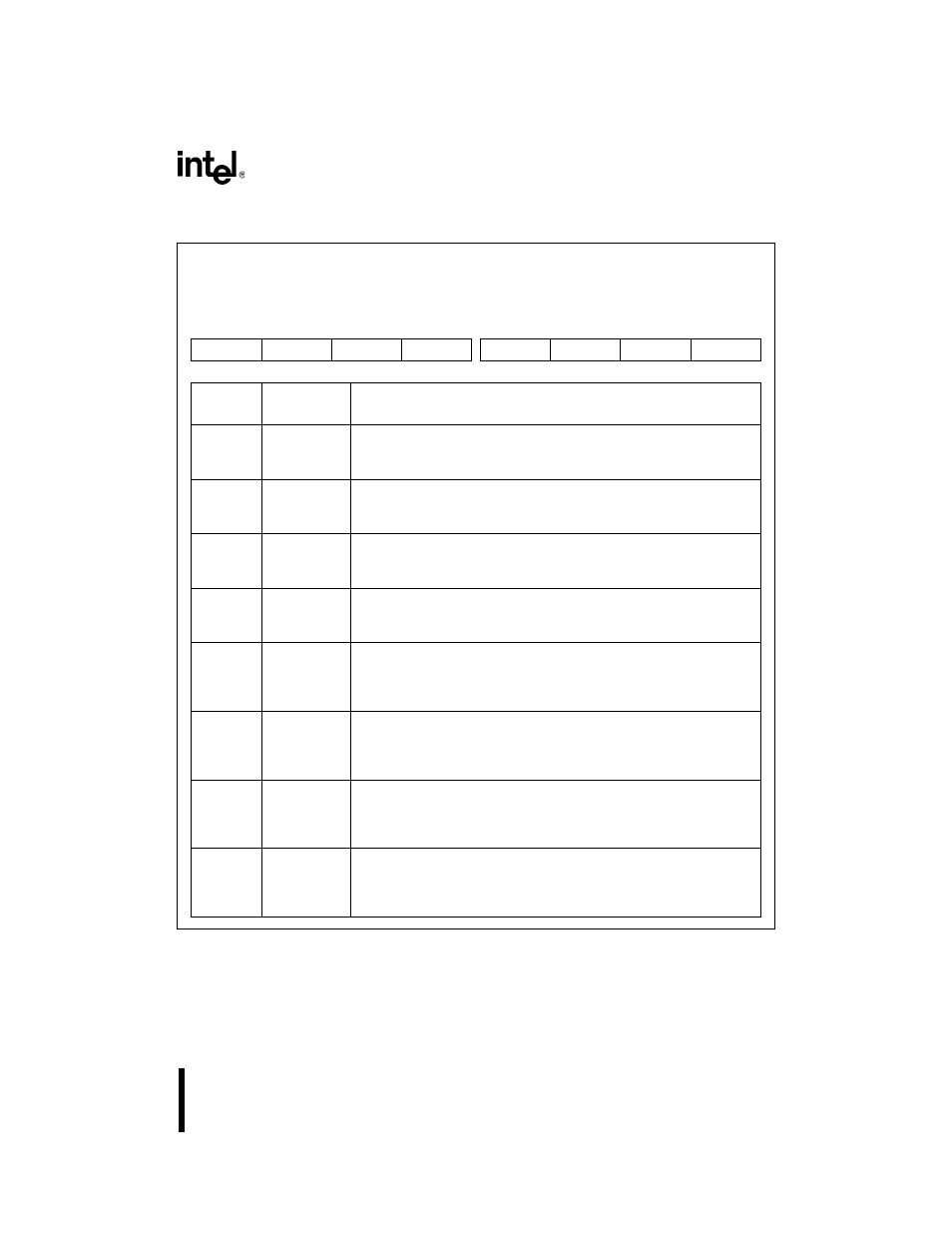
Modem Status
MSR0, MSR1
(read only)
Expanded Addr:
ISA Addr:
Reset State:
MSR0
MSR1
F4FEH
F8FEH
03FEH
02FEH
X0H
X0H
7
0
DCD
RI
DSR
CTS
DDCD
TERI
DDSR
DCTS
Bit
Number
Bit
Mnemonic
Function
7
DCD
Data Carrier Detect:
This bit is the complement of the data carrier detect (DCD
n#) input. In
diagnostic test mode, this bit is equivalent to MCR
n.3 (OUT2).
6
RI
Ring Indicator:
This bit is the complement of the ring indicator (RI
n#) input. In diagnostic
test mode, this bit is equivalent to MCR
n.2 (OUT1).
5
DSR
Data Set Ready:
This bit is the complement of the data set ready (DSR
n#) input. In
diagnostic test mode, this bit is equivalent to MCR
n.0 (DTR).
4
CTS
Clear to Send:
This bit is the complement of the clear to send (CTS
n#) input. In
diagnostic test mode, this bit is equivalent to MCR
n.1 (RTS).
3
DDCD
Delta Data Carrier Detect:
When set, this bit indicates that the DCD
n# input has changed state
since the last time this register was read. Reading this register clears
this bit.
2
TERI
Trailing Edge Ring Indicator:
When set, this bit indicates that the RI
n# input has changed from a low
to a high state since the last time this register was read. Reading this
register clears this bit.
1
DDSR
Delta Data Set Ready:
When set, this bit indicates that the DSR
n# input has changed state
since the last time this register was read. Reading this register clears
this bit.
0
DCTS
Delta Clear to Send:
When set, this bit indicates that the CTS
n# input has changed state
since the last time this register was read. Reading this register clears
this bit.