3 chip-select address registers, Figure 146. chip-select high address register (cs – Intel 386 User Manual
Page 452
14-17
CHIP-SELECT UNIT
14.4.3 Chip-select Address Registers
The Address Register of each chip-select channel defines the address block that the channel re-
sponds to during an access. The value in this register is compared to A25:11 of the processor bus
during a memory access and to A15:1 during an I/O access. A bus cycle whose address matches
the non-masked (see “Chip-select Mask Registers” on page 14-19) bits of the Address Register
causes the respective chip-select channel to have an address match. Even if there is an address
match, whether or not the CSU activates the channel depends on the values of the channel’s SMM
address and mask bits (CASMM and CMSMM) and the chip-select channel enable bit (CSEN).
The CASMM and CMSMM bits determine whether or not the channel is activated when the pro-
cessor is operating in SMM.
Write a channel’s 15-bit address to the chip-select address registers. These bits are masked by the
channel’s 15-bit mask.
NOTE
When a chip-select channel is activated, it either asserts a chip-select signal,
controls wait states and READY# generation, or both.
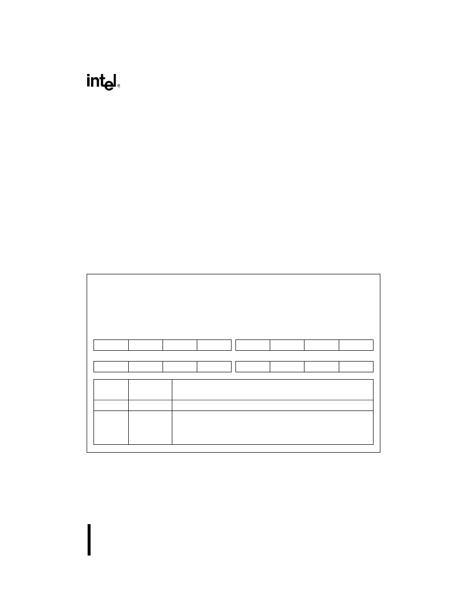
Figure 14-6. Chip-select High Address Register (CS
n
ADH, UCSADH)
Chip-select High Address
CS
nADH (n = 0–6), UCSADH
(read/write)
Expanded Addr:
ISA Addr:
Reset State:
F402H, F40AH
F412H, F41AH
F422H, F42AH
F432H, F43AH
—
0000H (CS
nADH)
FFFFH (UCSADH)
15
8
—
—
—
—
—
—
CA15
CA14
7
0
CA13
CA12
CA11
CA10
CA9
CA8
CA7
CA6
Bit
Number
Bit
Mnemonic
Function
15–10
—
Reserved; for compatibility with future devices, write zeros to these bits.
9–0
CA15:6
Chip-select Channel Address Upper Bits:
Defines the upper 10 bits of the channel’s 15-bit address. The address
bits CA15:6 and the mask bits CM15:6 form a masked address that is
compared to memory address bits A25:16 or I/O address bits A15:6.