1 pin configuration, Figure 163. port n configuration register (pncfg), Table 163. control register values for i/o port p – Intel 386 User Manual
Page 486
16-7
INPUT/OUTPUT PORTS
16.2.1 Pin Configuration
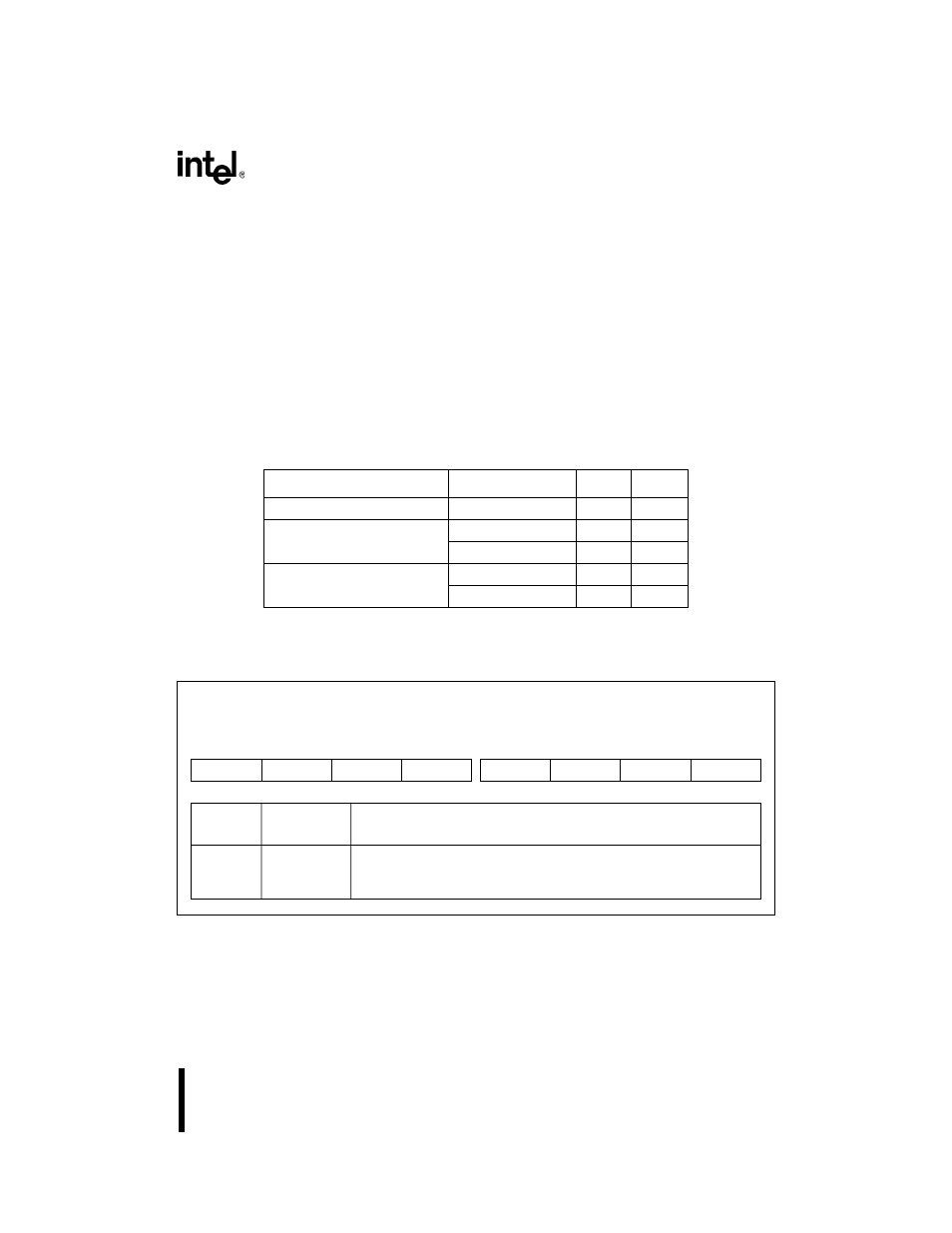
You select the operating mode of each pin by writing to the associated bit in the PnCFG registers
(Figure 16-3 gives an abbreviated version of these registers; for the complete register descrip-
tions, see Appendix D). Setting a bit selects peripheral mode; clearing a bit selects I/O mode. In-
ternal peripherals control pins configured for peripheral mode, while the PnDIR (Figure 16-4)
and PnLTC (Figure 16-5) registers control pins configured for I/O mode. Table 16-3 shows the
PnDIR and PnLTC register values that determine the pin direction and state.
NOTE
You must program both registers to correctly configure the pins.
Regardless of the pin’s configuration, you can read the PnPIN registers (Figure 16-6) to determine
the current pin state.
Figure 16-3. Port
n
Configuration Register (P
n
CFG)
Table 16-3. Control Register Values for I/O Port Pin Configurations
Desired Pin Configuration
Desired Pin State
P
nDIR
P
nLTC
High-impedance input
high impedance
1
1
Open-drain output
high impedance
1
1
0
1
0
Complementary output
1
0
1
0
0
0
Port
n Configuration
P
nCFG (n=1–3)
(read/write)
Expanded Addr:
ISA Addr:
Reset State:
F820H, F822H, F824H
—
00H
7
0
PM7
PM6
PM5
PM4
PM3
PM2
PM1
PM0
Bit
Number
Bit
Mnemonic
Function
7–0
PM7:0
Pin Mode:
0 = Places pin in I/O mode, controlled by P
nDIR and PnLTC registers.
1 = Places pin in peripheral mode, controlled by the internal peripheral