D.24 icw2 (master and slave), D.25 icw3 (master) – Intel 386 User Manual
Page 594
D-29
SYSTEM REGISTER QUICK REFERENCE
D.24 ICW2 (MASTER AND SLAVE)
D.25 ICW3 (MASTER)
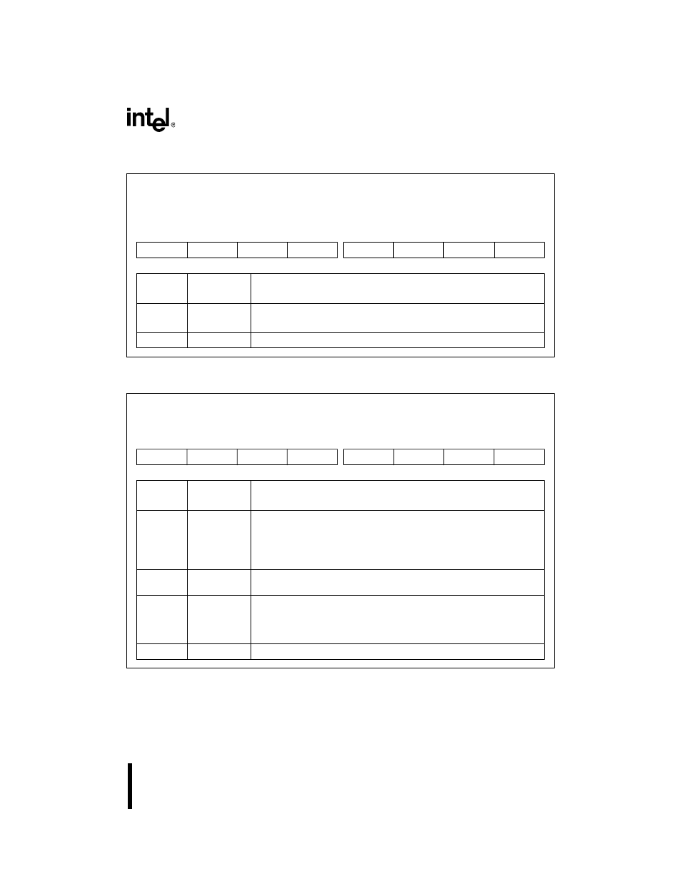
Initialization Command Word 2
ICW2 (master and slave)
(write only)
Expanded Addr:
ISA Addr:
Reset State:
master
slave
F021H
F0A1H
0021H
00A1H
XXH
XXH
7
0
T7
T6
T5
T4
T3
0
0
0
Bit
Number
Bit
Mnemonic
Function
7–3
T7:3
Base Interrupt Type:
Write the base interrupt vector’s five most-significant bits to these bits.
2–0
T2:0
Clear these bits to guarantee device operation.
Initialization Command Word 3
ICW3 (master)
(write only)
Expanded Addr:
ISA Addr:
Reset State:
F021H
0021H
XXH
7
0
S7
S6
S5
S4
S3
S2
S1
0
Bit
Number
Bit
Mnemonic
Function
7–3
S7:3
Slave IRs
0 = No slave 8259A is attached to the corresponding IR signal of the
master.
1 = A slave 82C59A is attached to the corresponding IR signal of the
master.
2
S2
0 = Internal slave not used
1 = Internal slave is cascaded from the master’s IR2 signal.
1
S1
Slave IRs
0 = No slave 8259A is attached to the master through the IR1 signal of
the master.
1 = A slave 82C59A is attached to the IR1 signal of the master.
0
—
Clear this bit to guarantee device operation.