5 ending dma transfers, Figure 125. changing the priority of the dma chan – Intel 386 User Manual
Page 345
Intel386™ EX EMBEDDED MICROPROCESSOR USER’S MANUAL
12-10
control request, the bus arbiter services these requests by issuing an internal hold signal request-
ing control of the bus from the core. The core returns an internal hold acknowledge signal to the
arbiter when bus ownership is granted. The arbiter then issues an acknowledge signal to the re-
questing device.
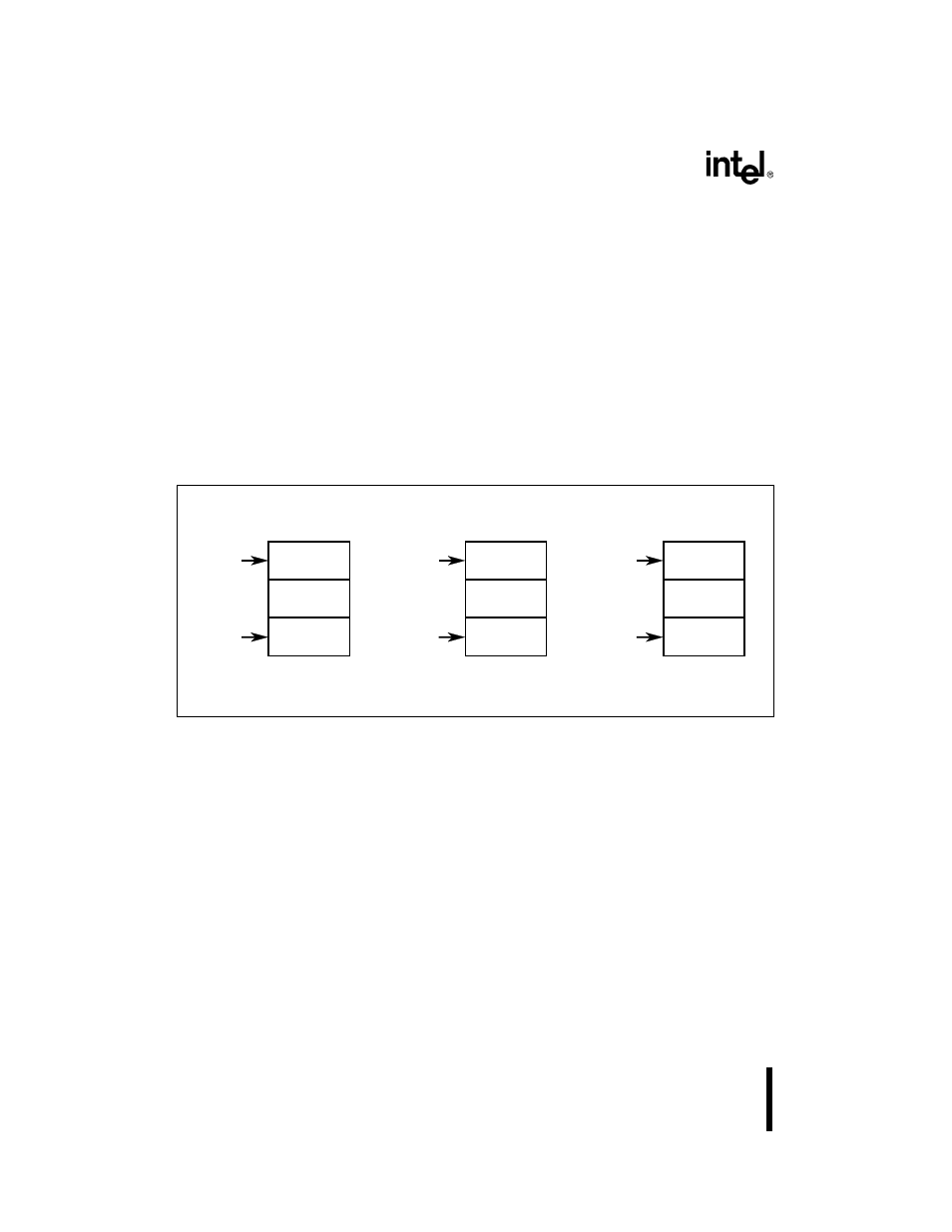
Refresh requests always have the highest priority, while the priority structure of the other three
requests is configurable. By default, DMA channel 0 requests have the next highest priority, fol-
lowed by DMA channel 1 requests, and external bus master requests There are two methods for
changing the priority of the DMA and external bus requests, low-priority selection or rotation.
The priority requests are programmed in the DMACMD2 register (see Figure 12-24). The low-
priority selection method allows you to assign a particular request to the lowest priority level.
With the rotation method, a request is automatically assigned to the lowest priority level after it
gains bus control. The rotation method allows requesting devices to share the system bus more
evenly. With both methods, the other request priority levels are adjusted in a circular manner (see
Figure 12-5).
Figure 12-5. Changing the Priority of the DMA Channel and External Bus Requests
12.2.5 Ending DMA Transfers
When a channel’s byte count expires, the buffer transfer is complete and the end-of-process
(EOP#) output is activated (Figure 12-6). A buffer transfer can be terminated before the byte
count expires by activating the EOP# input. The channel can sample the EOP# input synchro-
nously or asynchronously. With synchronous sampling, the channel samples EOP# at the end of
the last state of every data transfer. With asynchronous sampling, the DMA samples the inputs at
the beginning of every state of requester access, then waits until the end of the state to act on the
input. Figure 12-7 illustrates terminating a buffer transfer by activating the EOP# input; the figure
shows both asynchronous and synchronous EOP# sampling. EOP# sampling is programmed in
the DMACMD2 register (Figure 12-24).
DMA
Channel 0
Highest
Level
Lowest
Level
DMA
Channel 1
External Bus
Master
Low-priority
Select
Specified
Lowest
Level
Default
Rotating
Becomes
Highest
Level
Assigned
Lowest
Level
After Gaining
Bus Control
A2532-01
DMA
Channel 0
DMA
Channel 1
External Bus
Master
DMA
Channel 0
DMA
Channel 1
External Bus
Master
Becomes
Highest
Level