Figure 32. the intel386™ cx processor internal bl, Core overview – Intel 386 User Manual
Page 46
3-3
CORE OVERVIEW
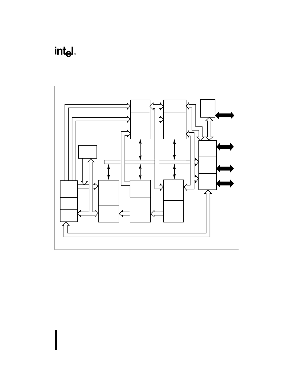
Figure 3-2 shows the internal architecture of the Intel386 CX processor.
Figure 3-2. The Intel386™ CX Processor Internal Block Diagram
A2851-02
3-Input
Adder
Descriptor
Register
Limit and
Attribute
PLA
Instruction
Decoder
3 Decoded
Instruction
Queue
Prefetcher
Limit
Checker
16 Byte
Code
Queue
Code
Stream
Barrel
Shifter,
Adder
Multiply/
Divide
Register
File
ALU
Decode
and
Sequencing
Control
ROM
ALU
Control
Protection
Test
Unit
32
Dedicated ALU Bus
32
32
32
Control
Instruction
Predecode
Instruction
Prefetch
Linear Address Bus
Displacement Bus
Adder
Page
Cache
Control and
Attribute
PLA
MUX/
Transceivers
Pipeline/
Bus Size
Control
Address
Driver
Request
Prioritizer
Internal Control Bus
32
32
Paging Unit
Core Plus
Unit
Segmentation Unit
Effective Address Bus
Effective Address Bus
32
32
Physical Address Bus
32
HOLD, INTR, NMI,
ERROR#,BUSY#,
RESET, HLDA,
SMI#, SMIACT#,
PEREQ
BE0#, BE1#,
A25:1
M/IO#, D/C#,
W/R#, LOCK#,
ADS#, NA#,
READY#
D15:0
Code fetch / Page Table Fetch
Control
Status
Flags
- 41210 (64 pages)
- 8xC251TQ (20 pages)
- ENTERPRISE PRINTING SYSTEM (EPS) 4127 (84 pages)
- U3-1L (20 pages)
- 80960HA (104 pages)
- X58 (54 pages)
- ESM-2850 2047285001R (91 pages)
- ATOM US15W (54 pages)
- D915GVWB (4 pages)
- XP-P5CM-GL (28 pages)
- AX965Q (81 pages)
- CORETM 2 DUO MOBILE 320028-001 (42 pages)
- CV700A (63 pages)
- 80C188EA (50 pages)
- X25-M (28 pages)
- XP-P5IM800GV (26 pages)
- IB868 (60 pages)
- D865GVHZ (88 pages)
- IB865 (64 pages)
- Altera P0424-ND (1 page)
- 8086-2 (30 pages)
- IXDP465 (22 pages)
- IWILL P4D (104 pages)
- GA-8I955X PRO (88 pages)
- FSB400 (PC2100) (96 pages)
- D845GLAD (4 pages)
- NAR-3041 (1 page)
- 87C196CA (136 pages)
- G52-M6734XD (74 pages)
- A96134-002 (10 pages)
- Express Routers 9000 (8 pages)
- 82540EP (45 pages)
- D865GLC (94 pages)
- IB850 (69 pages)
- MB898RF (62 pages)
- Arima LH500 (78 pages)
- V09 (33 pages)
- I/O Processor (22 pages)
- M600 (110 pages)
- SE7520JR2 (63 pages)
- SERVER BOARD S5520HCT (30 pages)
- Extensible Firmware Interface (1084 pages)
- GA-8IPXDR-E (70 pages)
- D845EBG2 (4 pages)
- AW8D (80 pages)