3 divisor latch registers (dlln and dlhn), Figure 1112. divisor latch registers (dlln and dl – Intel 386 User Manual
Page 309
Intel386™ EX EMBEDDED MICROPROCESSOR USER’S MANUAL
11-22
11.3.3 Divisor Latch Registers (DLL
n and DLHn)
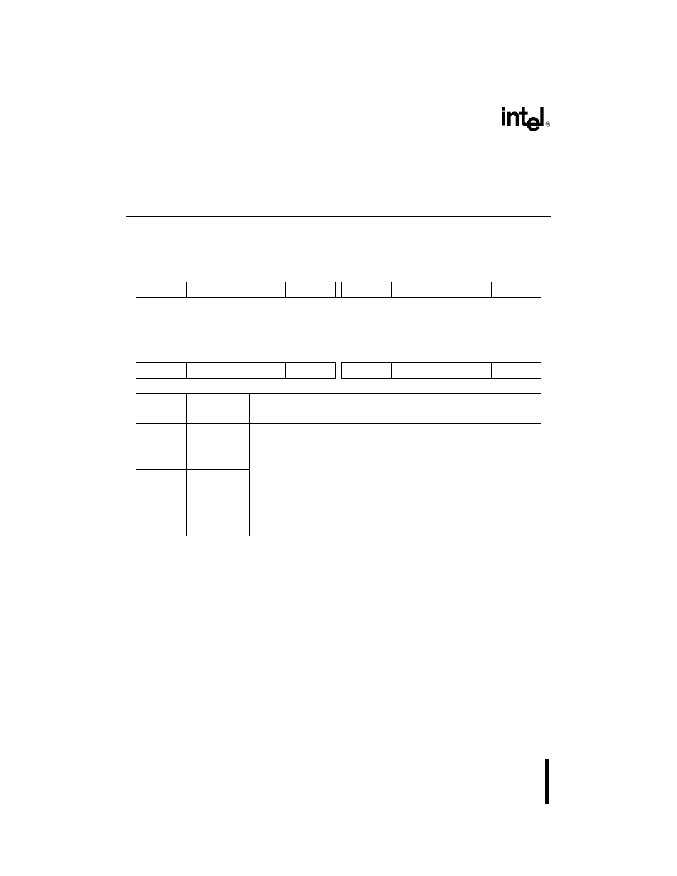
Use these registers to program the baud-rate generator’s output frequency. The baud-rate gener-
ator’s output determines the transmitter and receiver bit times.
Figure 11-12. Divisor Latch Registers (DLL
n
and DLH
n
)
Divisor Latch Low
DLL0, DLL1
(read/write)
Expanded Addr:
ISA Addr:
Reset State:
DLL0
DLL1
F4F8H
F8F8H
03F8H
02F8H
02H
02H
7
0
LD7
LD6
LD5
LD4
LD3
LD2
LD1
LD0
Divisor Latch High
DLH0, DLH1
(read/write)
Expanded Addr:
ISA Addr:
Reset State:
DLH0
DLH1
F4F9H
F8F9H
03F9H
02F9H
00H
00H
7
0
UD15
UD14
UD13
UD12
UD11
UD10
UD9
UD8
Bit
Number
Bit
Mnemonic
Function
DLL
n
(7–0)
LD7:0
Lower 8 Divisor and Upper 8 Divisor Bits:
Write the lower 8 divisor bits to DLL
n and the upper 8 divisor bits to
DLH
n. The baud-rate generator output is a function of the baud-rate
generator input (BCLKIN) and the 16-bit divisor.
bit rate (shifting rate) = baud-rate generator output frequency/16
DLH
n
(7–0)
UD15:8
NOTE:
The divisor latch registers share address ports with other SIO registers. Bit 7 (DLAB) of
LCR
n must be set in order to access the divisor latch registers.
If DLL = DLH = 00H, baud-rate generator ouput frequency = 0 (stops clock).
baud-rate generator output frequency
BCLKIN frequency
diviso r
-----------------------------------------------------
=