10 interrupt request register (irr), 11 in-service register (isr), 12 poll status byte (poll) – Intel 386 User Manual
Page 227: Figure 916. poll status byte (poll)
Intel386™ EX EMBEDDED MICROPROCESSOR USER’S MANUAL
9-28
9.3.10 Interrupt Request Register (IRR)
This 8-bit, read-only register contains the levels requesting an interrupt to be acknowledged. It is
accessed using OCW3 (see Figure 9-15). The highest request level is reset from the IRR when an
interrupt is acknowledged. Bits 7:0 of this register are the pending bits, respectively, of interrupt
requests IR7:0.
9.3.11 In-Service Register (ISR)
This 8-bit, read-only register contains the priority levels that are being serviced. It is accessed us-
ing OCW3 (see Figure 9-15). The ISR is updated when an End-of-Interrupt command is issued.
Bits 7:0 of this register are the in-service bits, respectively, of interrupt requests IR7:0.
9.3.12 Poll Status Byte (POLL)
Read the poll status byte after issuing a poll command to determine whether any of the devices
connected to the 82C59A require servicing. Once the polling bit is set in OCW3, the Poll Status
Byte of a particular 82C59A can be read by doing an access to any of the four addresses of that
82C59A.
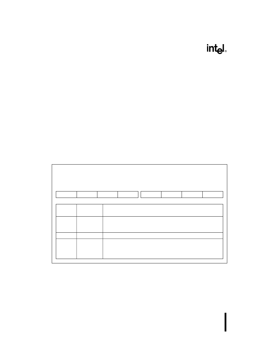
Figure 9-16. Poll Status Byte (POLL)
Poll Status Byte
POLL (master and slave)
(read only)
Expanded Addr:
ISA Addr:
Reset State:
master
slave
F020H
F0A0H
0020H
00A0H
XXH
XXH
7
0
INT
—
—
—
—
L2
L1
L0
Bit
Number
Bit
Mnemonic
Function
7
INT
Interrupt Pending:
0 = No request pending.
1 = Indicates that a device attached to the 82C59A requires servicing.
6–3
—
Reserved. These bits are undefined.
2–0
L2:0
Interrupt Request Level:
When bit 7 is set, these bits indicate the highest-priority IR signal that
requires servicing. When bit 7 is clear, i.e., no request is pending, these
bits are indeterminate.