Table 183. example tap controller state selection – Intel 386 User Manual
Page 518
18-5
JTAG TEST-LOGIC UNIT
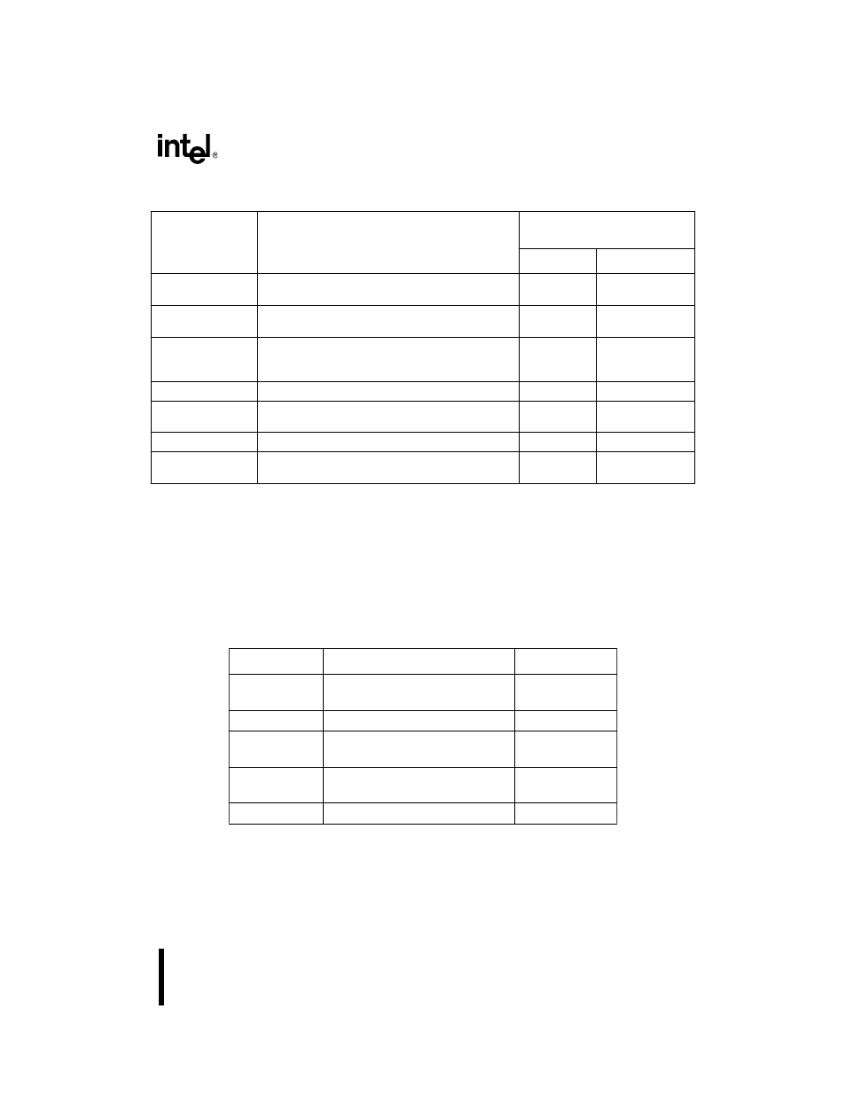
For example, assume that the TAP controller is in its test-logic-reset state and you want it to start
shifting the contents of the instruction register from TDI toward TDO (Shift-IR state). This state
change requires a zero, two ones, then two zeros on TMS at the next five rising edges of TCK
(see Table 18-3). By supplying the proper values in the correct sequence, you can move the TAP
controller from any state to any other state.
Select-IR-Scan
Test-logic is idle and the instruction register retains
its previous state.
Capture-IR
Test-Logic-Reset
Capture-IR
Loads the SAMPLE/PRELOAD instruction
instruction (0001) into the instruction register.
Shift-IR
Exit1-IR
Shift-IR
Shifts the SAMPLE/PRELOAD instruction one
stage toward TDO while shifting the new instruction
in from TDI on each rising edge of TCK.
Shift-IR
Exit1-IR
Exit1-IR
The instruction register retains its previous state.
Pause-IR
Update-IR
Pause-IR
The instruction register temporarily stops shifting
and retains its previous state.
Pause-IR
Exit2-IR
Exit2-IR
The instruction register retains its previous state.
Shift-IR
Update-IR
Update-IR
Latches the current instruction onto the instruction
register’s parallel output on the falling edge of TCK.
Run-Test/Idle
Select-DR-Scan
Table 18-3. Example TAP Controller State Selections
Initial State
TMS Value at TCK Rising Edge
Resulting State
Test-Logic-
Reset
0
Run-Test/Idle
Run-Test/Idle
1
Select-DR-Scan
Select-DR-
Scan
1
Select-IR-Scan
Select-IR-
Scan
0
Capture-IR
Capture-IR
0
Shift-IR
Table 18-2. TAP Controller State Descriptions (Sheet 2 of 2)
State
Description
Next State
(on TCK Rising Edge)
TMS = 0
TMS = 1
NOTE:
By convention, the abbreviation
DR stands for data register, and IR stands for instruction register.
The
active register is the register that the current instruction has placed in the serial path between
TDI and TDO.